Understanding the 6 Degrees of Freedom
The following is an excerpt from The CMM Handbook
Using The Correct CMM Alignment Principles
Understanding the principle of the 6 degrees of freedom is essential to aligning your part correctly on the Coordinate Measuring Machine (CMM). When a part is placed on the CMM the location of the part is not known. It must be defined by using several features known as datums.
These datums are defined on the blueprint and must be measured to define the part’s location to the CMM’s home position. If a program were written without a complete datum alignment all the linear locations in your program would come from the machines home position and not from the locations given on the blueprint. The subsequent parts would have to be placed in the exact location and alignment for your program to work. Writing a datum alignment routine at the beginning of your program will allow you to place the part anywhere on the CMM surface plate and will insure that your part will be aligned properly and your program will run correctly each time.
There will be three alignment functions used to define the datums (1) Orientation – this will use a 3d element to align the part to a spatial alignment. (2) Alignment – an element is used to align the part square to a CMM axis. (3) Origin – this will determine where the zero point is set. CMM softwares use alignment dialog boxes that allow you to set all the required datum elements at one time.
Words To Be Familiar With
Alignment – A part must be aligned to the CMM axes before you can begin to fully measure your part. The alignment is based on the datums specified on the blueprint. This alignment routine will square the part to the CMM and set the reference point (Origin) for all other dimensions to be referenced to.
Datum – A feature on the blueprint that is designated with a Datum letter. This feature is used to establish an origin that will be used to reference all other dimensions from.
Origin – The part’s zero point. The reference point on a part where the all the datums converge. The origin is where all other features are dimensioned from.
Coordinate System – After your alignment is complete and your origin is set this is known as a coordinate system.
Rotational – This degree of freedom allows the part to rotate about a given axis.
Translational – This degree of freedom allows the part to move transitional along an axis.
These principles constrain the 6 degrees of freedom.
6 Degrees of Freedom
When a part is held up in space it has “six degrees of freedom”, 3 Rotational and 3 Translational. The part can rotate about the X, Y, Z axes (rotational) and move along each of the three axes (translational). As shown below.
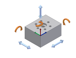
The part can rotate about the X, Y, Z axes and move along each of the three axes
In order to align a part to the CMM all degrees of freedom must be constrained, there are exceptions but, in our example, all must be constrained. For this example, we will place the part in a DRF, a datum reference frame. This will represent how we will constrain the degrees of freedom when we probe the part.
Placing the part on the surface plate or on a fixture constrains 3 degrees of freedom. The part can longer move up and down in Z (1 translation) or rotate about the X axis or about the Y axis (2 rotational).

Constraining 3 degrees of freedom
As you can see, we can still rotate about Z and move the part back and forth in the X and Y axes.
Constraining one side of the block will limit 2 more degrees of freedom. Removing the ability to rotate in the Z axis (1 rotational) and constrains the ability to move in the X axis (1 translational). The part can still move back and forth in the Y axis.

Constraining one side of the block will limit 2 more degrees of freedom.
Constraining the last degree of freedom requires restricting the back-and-forth motion of the last axis.

Restricting the back-and-forth motion of the last axis.
Now all 6 degrees of freedom have been constrained. You can see how this is accomplished on an open surface plate setup by merely pushing the part against a knee block or some sort of fixture. With CMM software the constraining of features is done with probing the part.