
You have choices, make the right choice

CMM Manager: Slot with MMC
Learn how to create VB Scripting to create a diameter within a slot that MMC can be applied to for position.
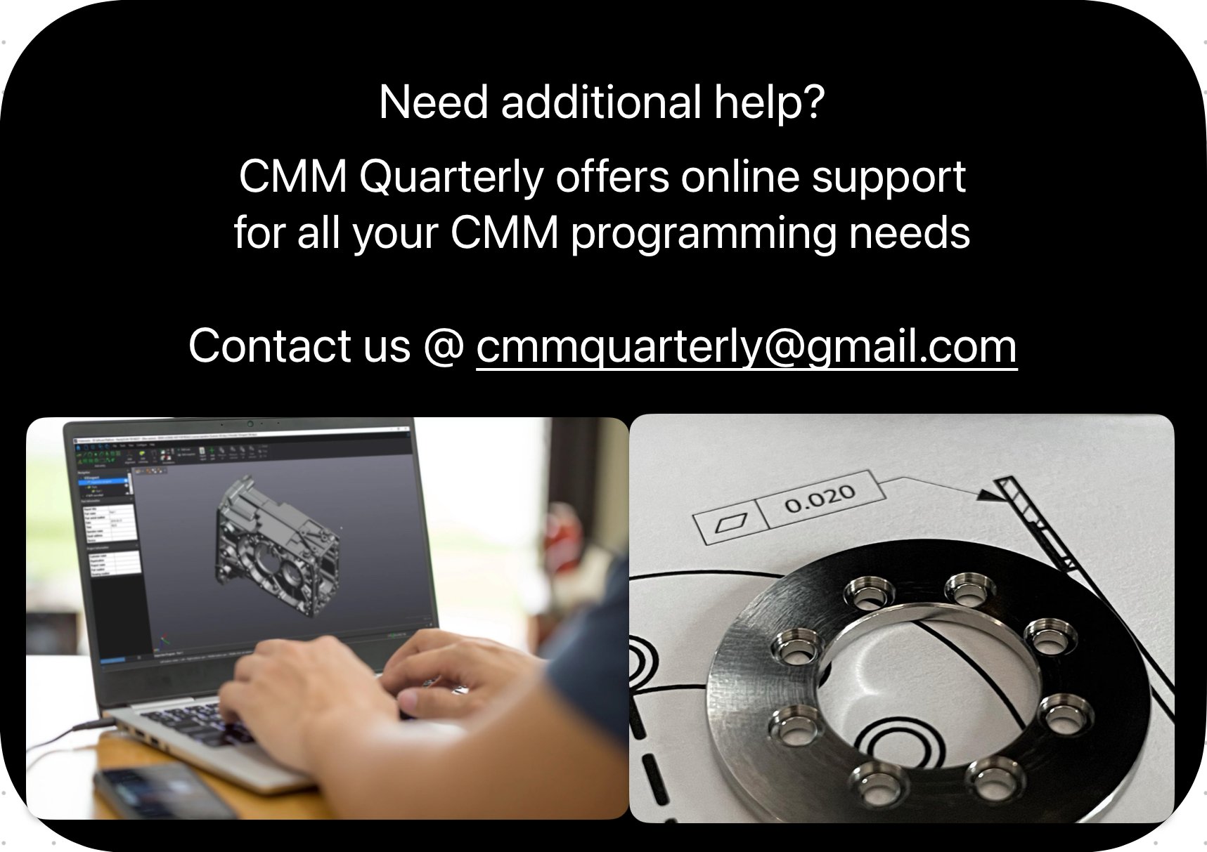

CMM Software Mentoring
At CMM Quarterly one on the services we provide is software mentoring. What is that? We can meet online for a couple of hours as many times as you like to go over topics., review your programs, etc…
CMM Software Mentoring
At CMM Quarterly one on the services we provide is software mentoring. What is that? We can meet online for a couple of hours as many times as you like to go over topics., review your programs, etc…
Do you have items in your cart?
Here is a discount code for purchases until the end of July

CMM Manager VB Scripting
Have you ever struggled with VB scripting in CMM Manager. This book will change that and elevate your cmm programming skills to a new level. This book will help you create practical dialog boxes like the one below.
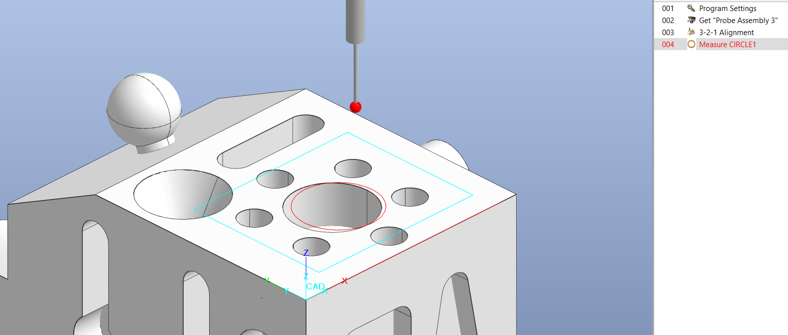
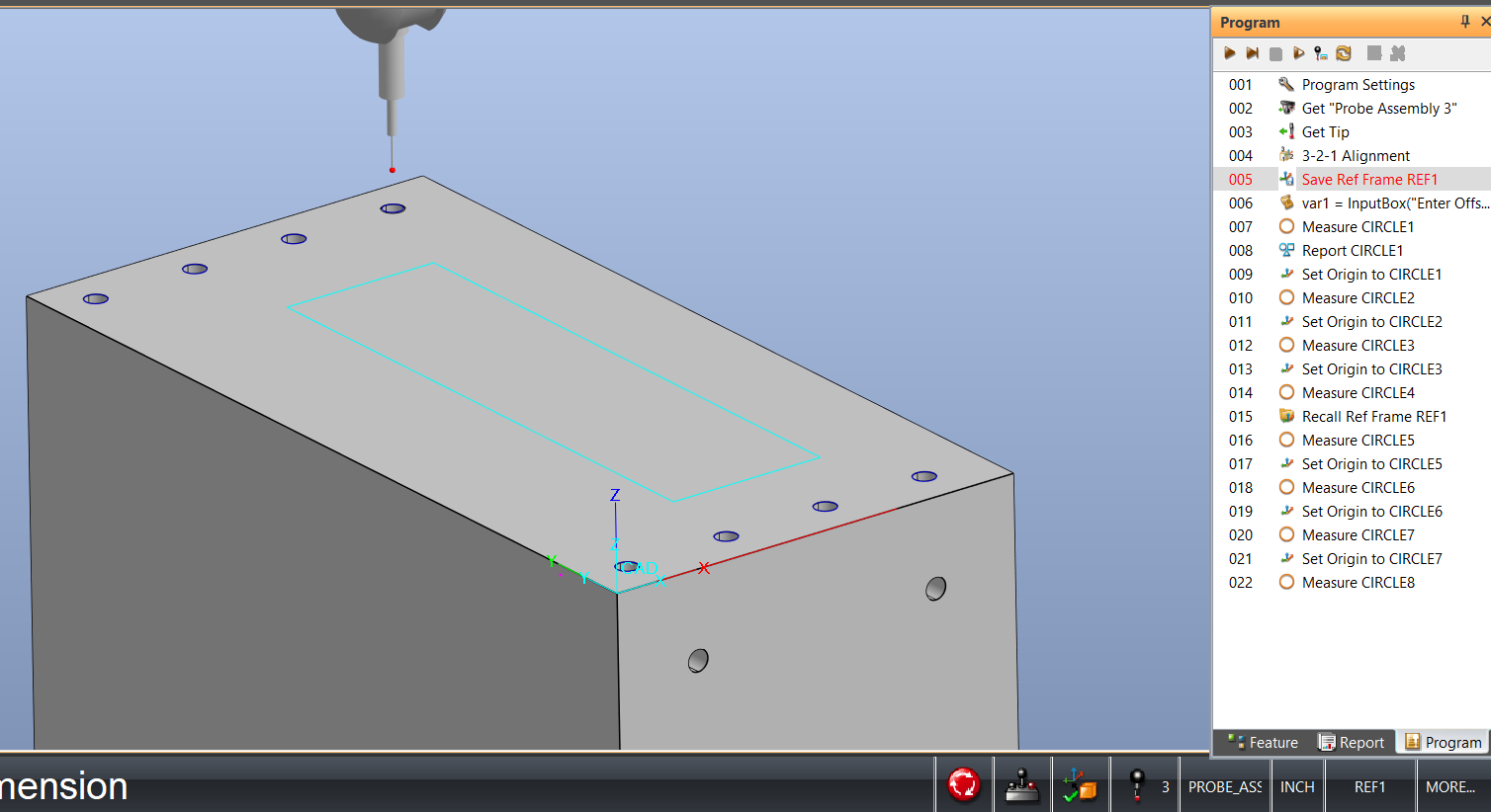
How to Create a VB Script Program to Better Locate Position of a Feature
The issue is, in our program if Circle1 is not in the correct location, due to machine targeting or various other reasons we will want to manually check the diameter of Circle1 and use this new location to check the diameter in CNC mode.
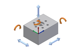
Understanding the 6 Degrees of Freedom
Understanding the principle of the 6 degrees of freedom is essential to aligning your part correctly on the Coordinate Measuring Machine (CMM). When a part is placed on the CMM the location of the part is not known. It must be defined by using several features known as datums.
Control Movement of Pattern of Holes Using VB Script
cmm-quarterly.squarespace.com/articles/control-movement-of-pattern-of-holes-using-VB-Script
How To: Operation Planner
Do you manufacture parts in distinct operations? Is the part also inspected after / during each of these distinct manufacturing operations? Are you creating unique CMM-Manager programs for each operation? If so, there is a better way