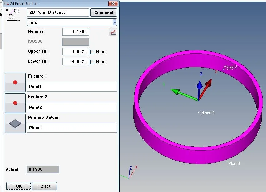
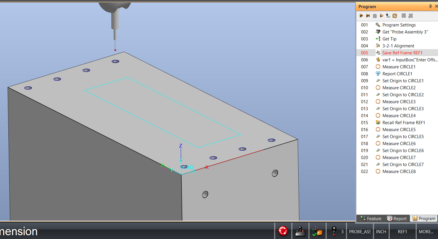
Calypso - Point Recall with Loop
This will create a wall thickness 360° around the part top and bottom 8 points each.
Program
Flatness - GD&T and Calypso Rev 3 Book
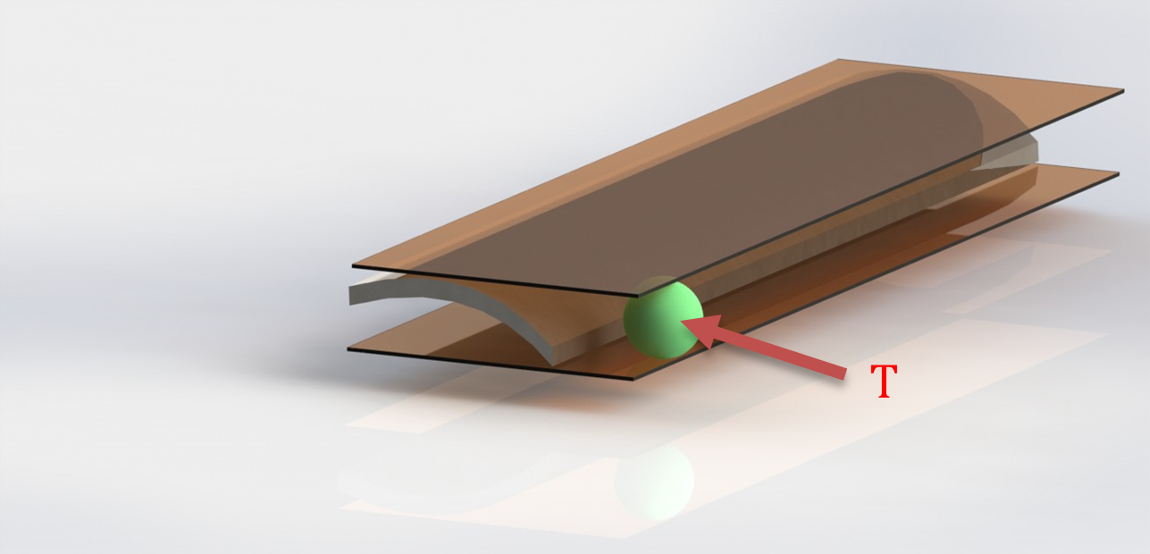
Flatness (form tolerance): the tolerance zone is limited by two parallel planes a distance t apart.
Implies: Straightness of the surface or Straightness of the derived median line
CMM Quarterly - who we are
CMM Quarterly has been around for 17+ years bringing CMM programmers and operators the real inside information they need. We have all read the ‘fluff’ pieces that some e-magazines put out or they own the site that puts out articles but wouldn’t know how to run a CMM to save their life.

Motorsport: Driven by speed
Formula One is an innovative and high performance arena where speed, precision and accuracy is of the essence at all times. To maintain pole position, Oracle Red Bull Racing has been in a long-term technical partnership with Hexagon’s Manufacturing Intelligence division. Machinery heard more at the F1 team’s Milton Keynes factory
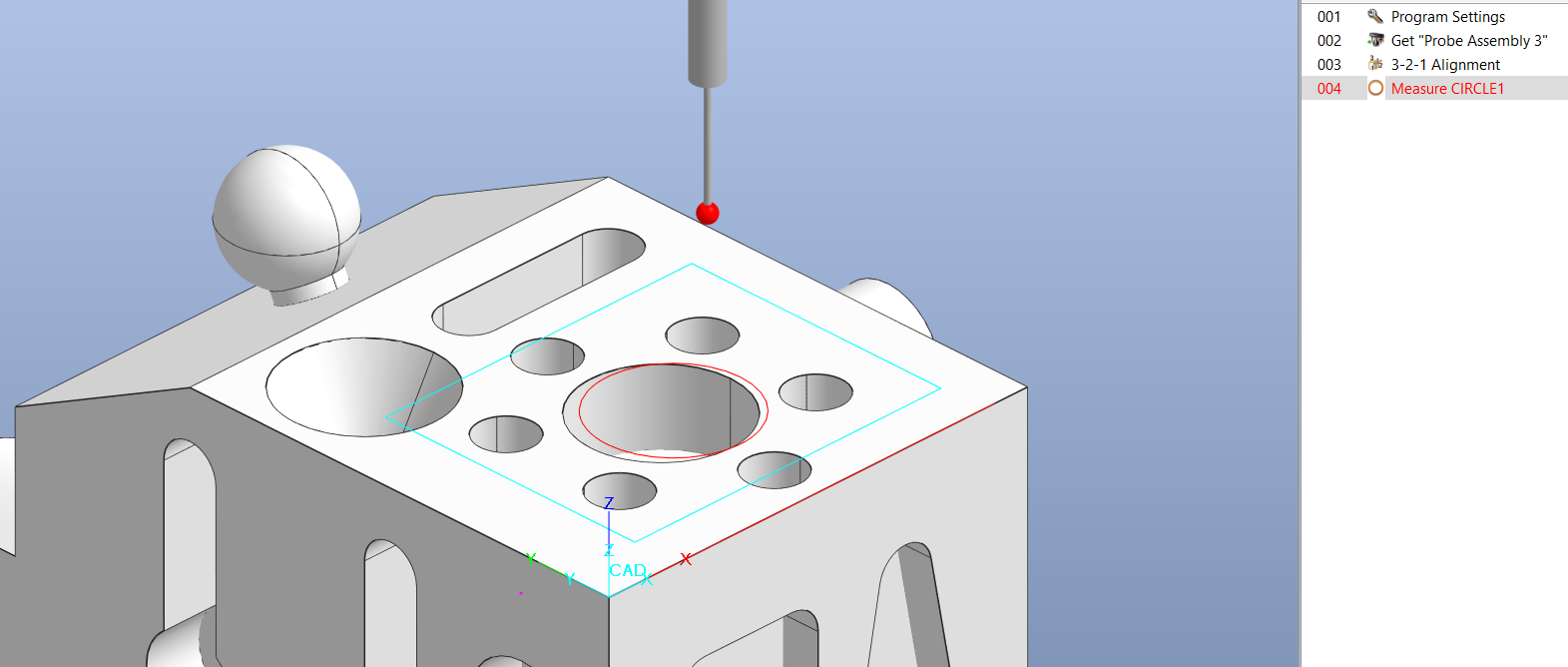
How to Create a VB Script Program to Better Locate Position of a Feature
The issue is, in our program if Circle1 is not in the correct location, due to machine targeting or various other reasons we will want to manually check the diameter of Circle1 and use this new location to check the diameter in CNC mode.
Added MCOSMOS C1 v4 Manual
We have added a MCOSMOS C1 version 4 training manual to our products.
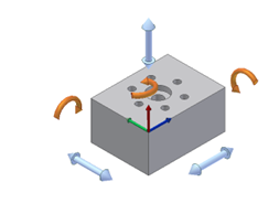
Understanding the 6 Degrees of Freedom
Understanding the principle of the 6 degrees of freedom is essential to aligning your part correctly on the Coordinate Measuring Machine (CMM). When a part is placed on the CMM the location of the part is not known. It must be defined by using several features known as datums.
Control Movement of Pattern of Holes Using VB Script
cmm-quarterly.squarespace.com/articles/control-movement-of-pattern-of-holes-using-VB-Script

Flexxbotics Integrates Hexagon Inspection Equipment
Flexxbotics, a supplier of workcell digitalization technologies for robot-driven manufacturing, has released FlexxCore, its advanced robotic machine tending in-line inspection connectivity compatible with Hexagon inspection equipment.

2-Day In-Person Public GD&T Training Event on July 9-10, 2024
This In-Person GD&T Fundamentals Public Training Course allows you to learn GD&T in 2-days - with a live in-person instructor, enabling you to complete training off site, without distractions from the office or home. In this course, we teach a simple framework for understanding how GD&T is used and why it improves the manufacturing process. Our GD&T Fundamentals course focuses on practical knowledge and uses real-world drawing examples throughout the class to practice what is learned.
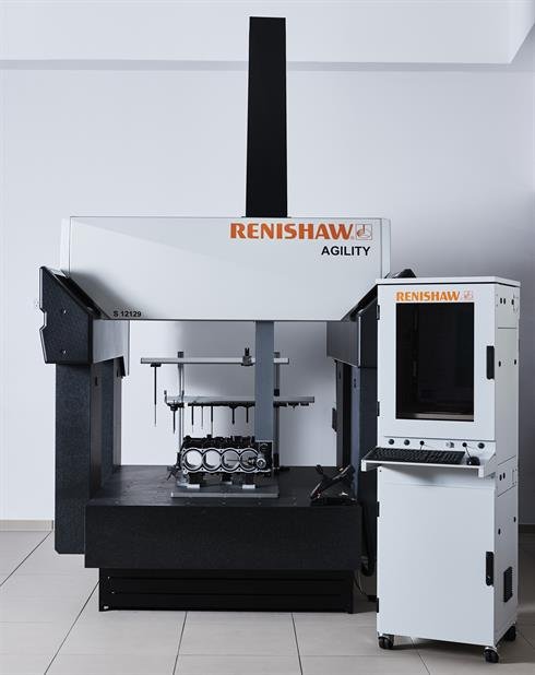
AGILITY S 5-axis multi-sensor CMMs for the shop floor
Designed for shop floor environments
The S range of CMMs provides the ability to accurately measure parts in shop floor environments without temperature control. The rapid data capture speeds provided by 5-axis measurement reduce inspection cycle times, helping production departments keep pace with high volume manufacture. The systems work well in both stand-alone and fully automated production lines.