
You have choices, make the right choice

CMM Software Mentoring
At CMM Quarterly one on the services we provide is software mentoring. What is that? We can meet online for a couple of hours as many times as you like to go over topics., review your programs, etc…
ZEISS announces software sales partnership with Artec 3D
ZEISS is cooperating with Artec 3D, a Luxemburg-based technology company that develops, manufactures, and distributes handheld and portable 3D scanners. Under the agreement, Artec 3D will offer ZEISS’ state-of-the-art inspection software as a valuable extension to their range of 3D scanning hardware. The combination of ZEISS software with Artec 3D scanners allows an increasing user group to benefit from an outstanding 3D solution for a broad range of metrology applications.
CMM Software Mentoring
At CMM Quarterly one on the services we provide is software mentoring. What is that? We can meet online for a couple of hours as many times as you like to go over topics., review your programs, etc…
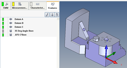
Calypso - Condition Based on Confirm Statement
What to expect. Yes, (it does exist) the CMM will measure the 35 Deg Bore. No, (does not exist) it will skip the 35 Deg Bore and move to the .875 diameter.
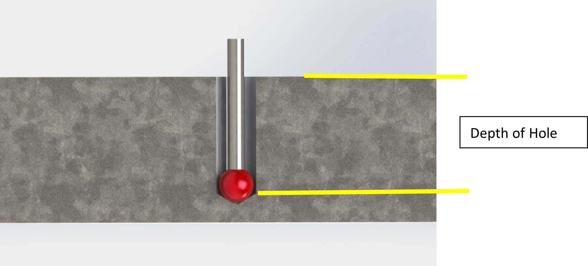
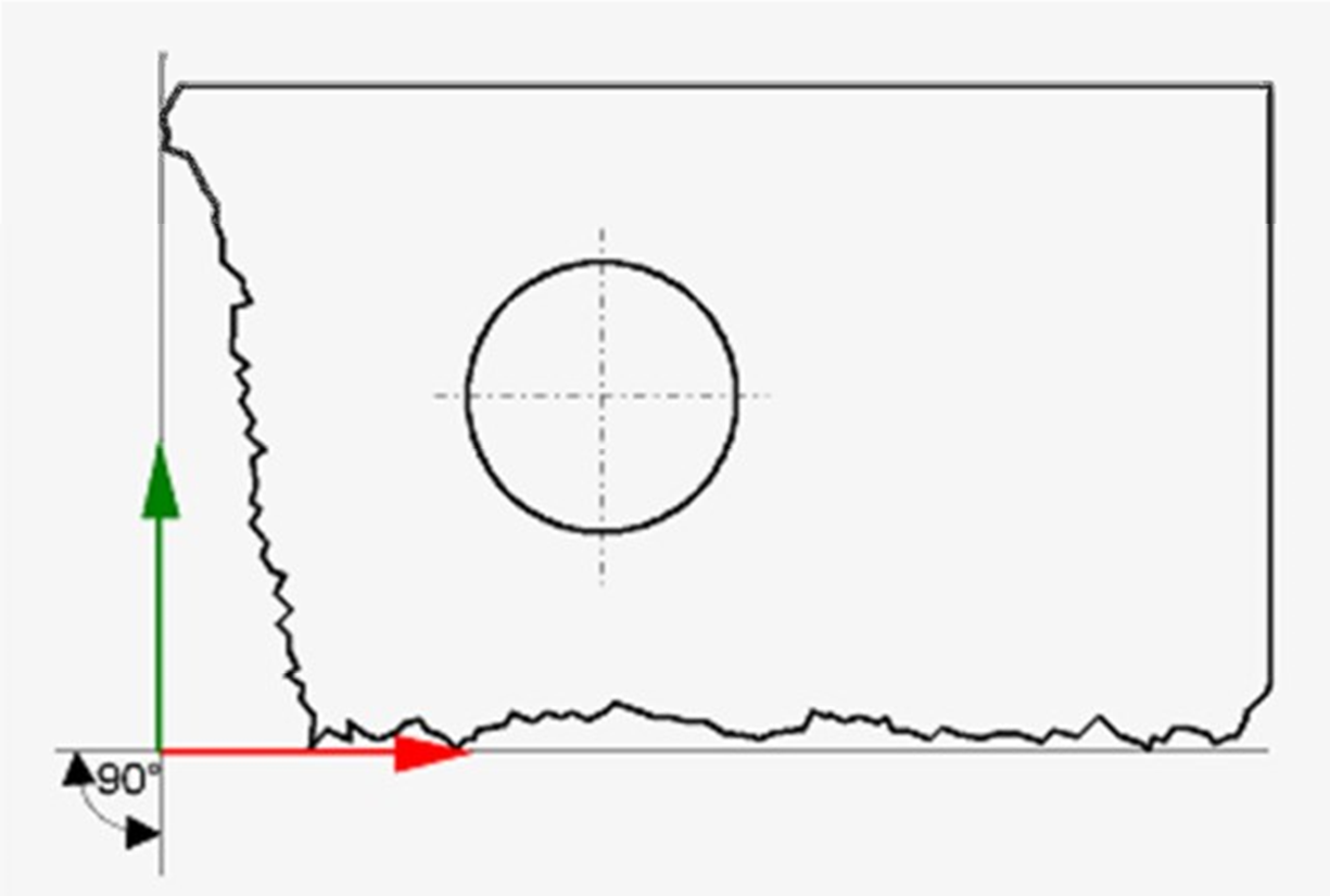
Calypso - Blind Hole Depth
This is an excerpt from the Calypso Handbook
To measure the depth of a blind hole we must calculate the depth by using this process.
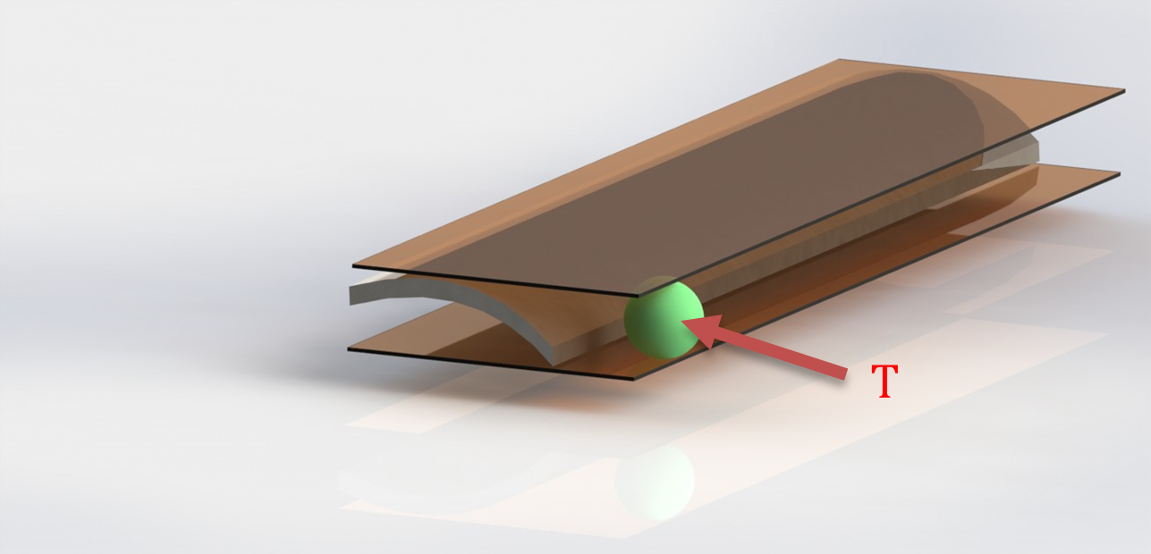
Calypso - Point Recall with Loop
This will create a wall thickness 360° around the part top and bottom 8 points each.
Program
Flatness - GD&T and Calypso Rev 3 Book
Flatness (form tolerance): the tolerance zone is limited by two parallel planes a distance t apart.
Implies: Straightness of the surface or Straightness of the derived median line
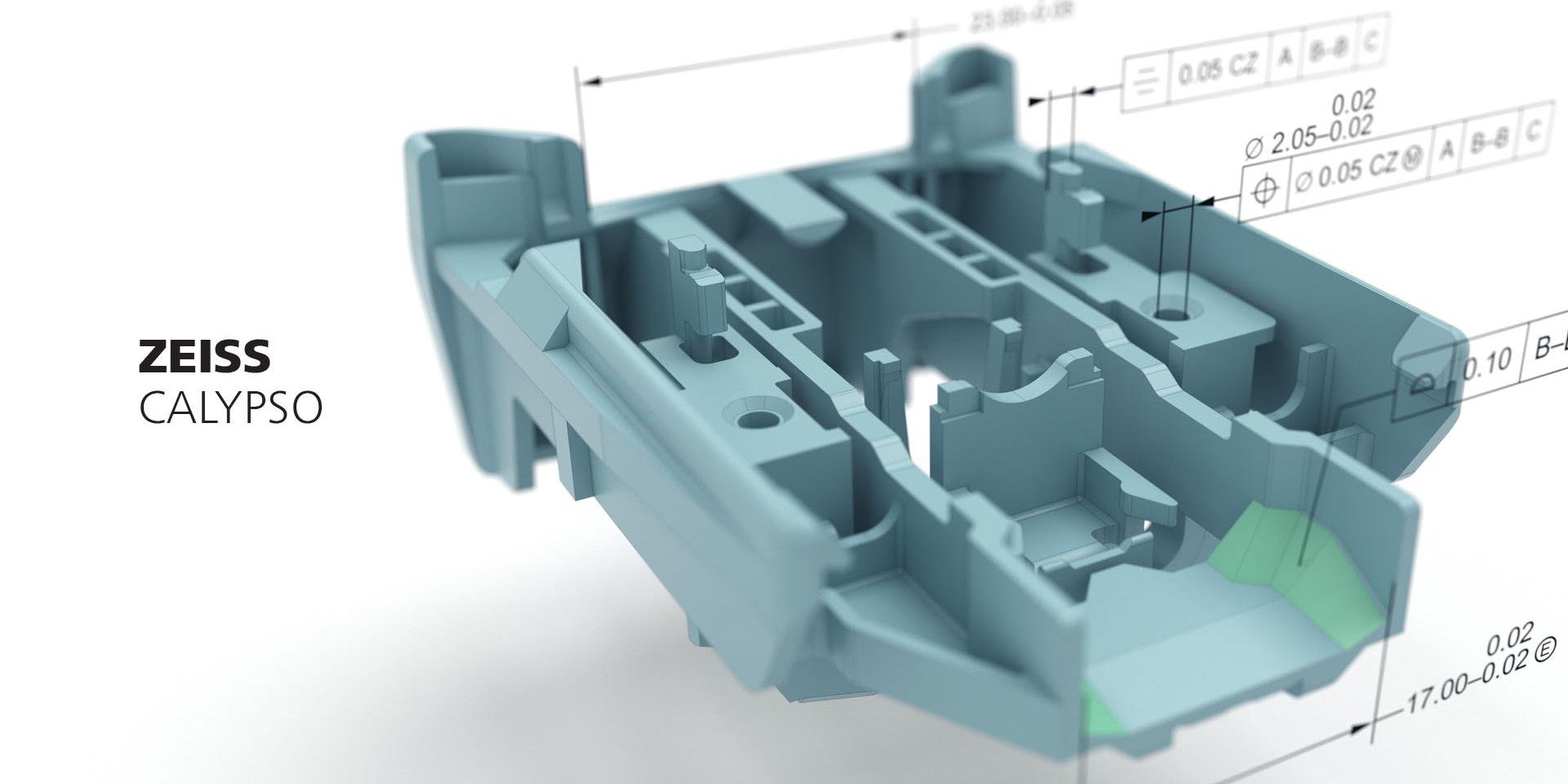
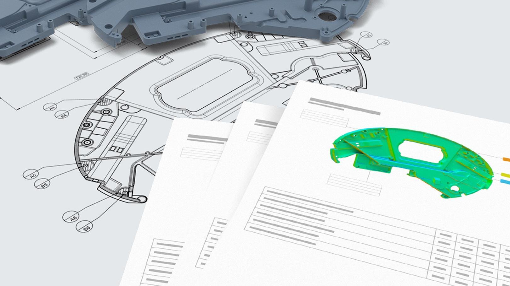
Higher Flexibility with Less Effort
To maintain their position as a market leader, many companies are committed to quality control – for example, by using coordinate measuring machines. However, only an ideal software makes a comprehensive and individual evaluation possible. ZEISS CALYPSO is the general measuring software enabling both tactile and optical measurements with ZEISS coordinate measuring machines as well as the verification and analysis of the resulting 3D data. The new software version has been released.
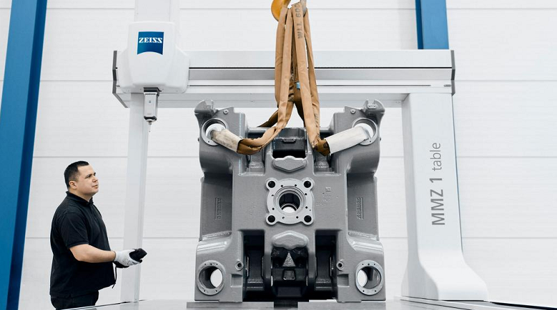
ZEISS Introduces Compact CMM for Precise Measurement of Large Volume Parts
ZEISS has launched the ZEISS MMZ 1 table CMM, designed specifically for large workpieces and applications that require highly accurate contact measurements. This machine excels in evaluating size, form, and location measurements with exceptional precision. Equipped with the ZEISS VAST XT gold probe head mounted on a silicon carbide ram, the ZEISS MMZ 1 offers enhanced temperature stability.
Form Datum - Calypso
What the Form Datum does is establish a FUNCTIONAL Datum Reference Frame coordinate system, similar to if you were setting up the primary, secondary, and tertiary datums on a functional checking gage. This is ONLY for a datum reference frame and does not modify how the base and secondary alignments evaluate their respective coordinate system. In the screen shot below, you can notice the different origin points are for a base alignment and datum reference frame.
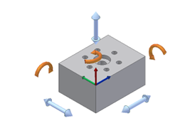
Understanding the 6 Degrees of Freedom
Understanding the principle of the 6 degrees of freedom is essential to aligning your part correctly on the Coordinate Measuring Machine (CMM). When a part is placed on the CMM the location of the part is not known. It must be defined by using several features known as datums.
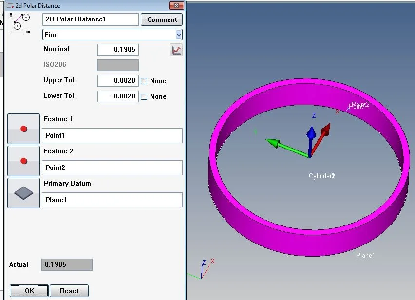
Cartesian Distance
In this example, the “Primary Datum” is the same as the “Spatial Rotation” and “Secondary Datum” is the same as the “Planar Rotation” inside an alignment. Selecting “Parallel To” or “Perpendicular” specifies the axis direction. i.e. the “X”, “Y” or “Z” axis
Alignment with Offset Plane
The offset plane can be used in an alignment construction. A good example of an offset plane is cast datum points, where they are rarely on the same plane.