
You have choices, make the right choice
Higher Flexibility with Less Effort
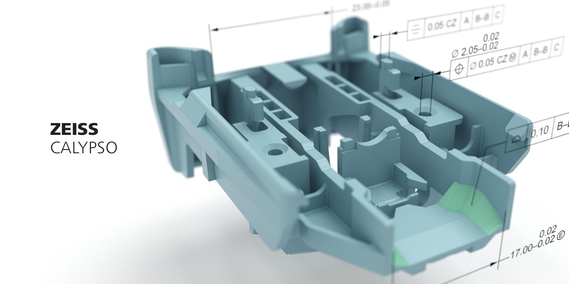
To maintain their position as a market leader, many companies are committed to quality control – for example, by using coordinate measuring machines. However, only an ideal software makes a comprehensive and individual evaluation possible. ZEISS CALYPSO is the general measuring software enabling both tactile and optical measurements with ZEISS coordinate measuring machines as well as the verification and analysis of the resulting 3D data. The new software version has been released.
ZEISS Introduces Compact CMM for Precise Measurement of Large Volume Parts
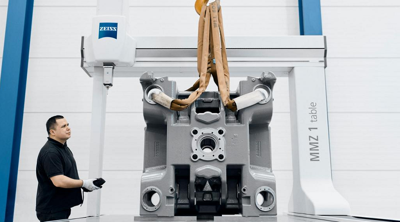
ZEISS has launched the ZEISS MMZ 1 table CMM, designed specifically for large workpieces and applications that require highly accurate contact measurements. This machine excels in evaluating size, form, and location measurements with exceptional precision. Equipped with the ZEISS VAST XT gold probe head mounted on a silicon carbide ram, the ZEISS MMZ 1 offers enhanced temperature stability.
Cartesian Distance
In this example, the “Primary Datum” is the same as the “Spatial Rotation” and “Secondary Datum” is the same as the “Planar Rotation” inside an alignment. Selecting “Parallel To” or “Perpendicular” specifies the axis direction. i.e. the “X”, “Y” or “Z” axis
Alignment with Offset Plane
The offset plane can be used in an alignment construction. A good example of an offset plane is cast datum points, where they are rarely on the same plane.