
You have choices, make the right choice
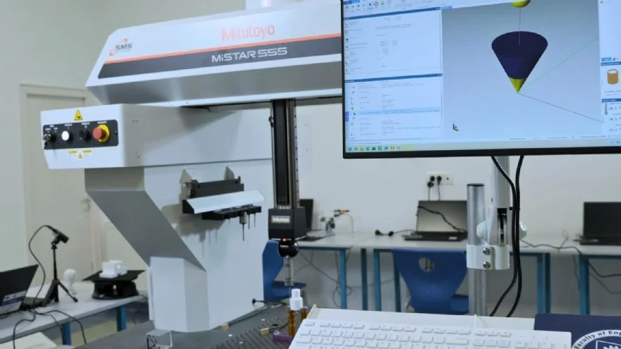
Mitutoyo supports future engineers at Babeș‑Bolyai University
With a tradition dating back to 1581, Babeș-Bolyai University, Cluj-Napoca – also known as UBB – is the oldest university in Romania, standing as one of the leading institutions of Romanian academia.
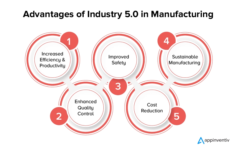
Synergizing Human Ingenuity and Machine Precision: The CMM’s Pivotal Role in Industry 5.0
As industries transition from the automation-heavy paradigms of Industry 4.0 to the more holistic vision of Industry 5.0, CMMs are being redefined through enhanced integration with human expertise, sustainability initiatives, and resilient operations.
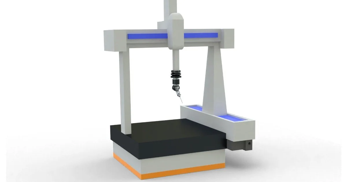
Is Your Quality Room The Issue When it Comes to Your Measurements
In the precision-driven world of manufacturing and quality control, Coordinate Measuring Machines (CMMs) stand as indispensable tools for ensuring dimensional accuracy and part conformity.
Ready launches ‘RUN’ – a flexible CMM for shopfloors
Italy-based Ready has introduced RUN, a new line of coordinate measuring machines (CMMs) designed specifically for use in production environments.
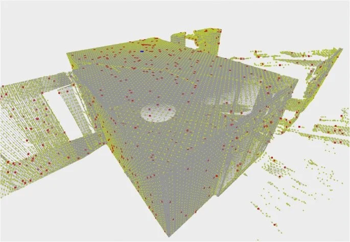
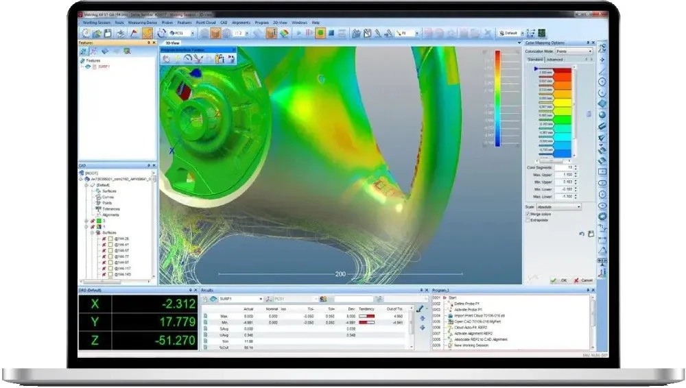
Understanding the GUM Methodology: Applications to Point Clouds in Coordinate Metrology
In the field of coordinate metrology, where precision is paramount, the accurate assessment of measurement uncertainty is essential for ensuring reliable results. The Guide to the Expression of Uncertainty in Measurement (GUM) provides a standardized framework for evaluating and expressing this uncertainty. Developed collaboratively by international metrology organizations, GUM has become the cornerstone for uncertainty analysis across various measurement disciplines, including those involving coordinate measuring machines (CMMs) and 3D scanning technologies.
Understanding ISO 10360 Standards for Coordinate Measuring Machines
The ISO 10360 series is an international set of standards developed by the International Organization for Standardization (ISO) to specify acceptance and reverification tests for Coordinate Measuring Machines (CMMs).

Education, Metrology and Manufacturing in Sync
Vincennes University, Vincennes, IN, a flagship HTEC (Haas Technology Education Center) and Flying S Inc, Palestine, IL, are an example of education working in lockstep with a real-world industry partner.
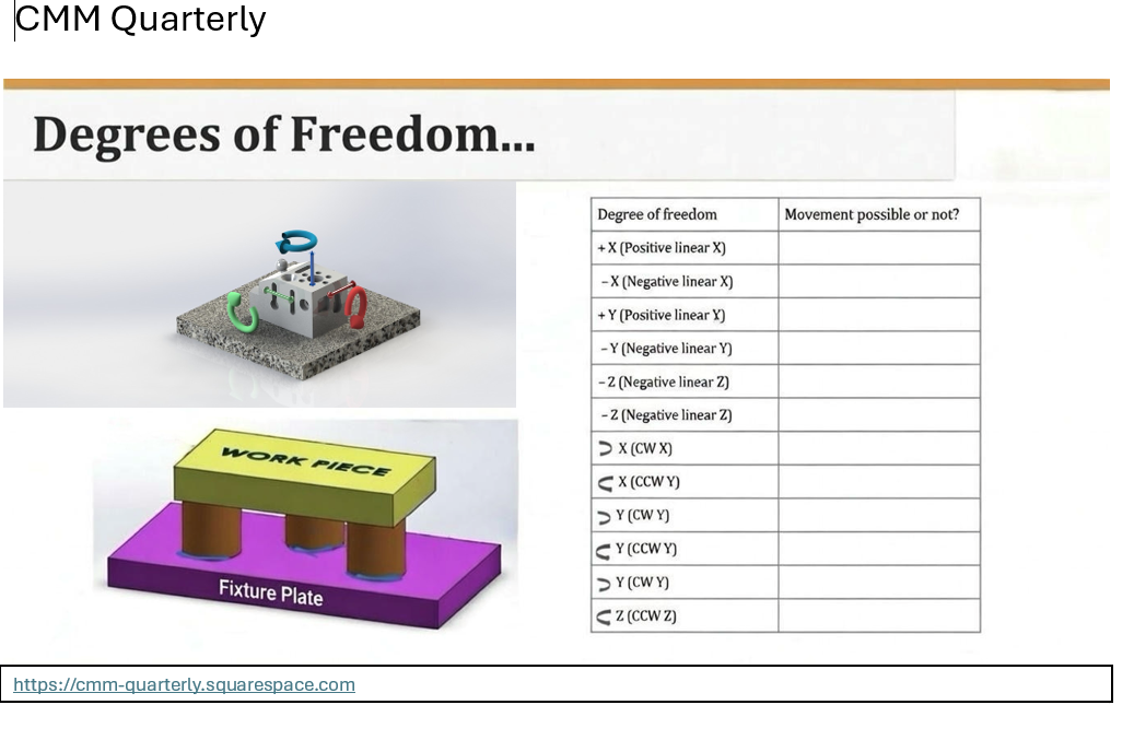
Degrees of Freedom Checklist
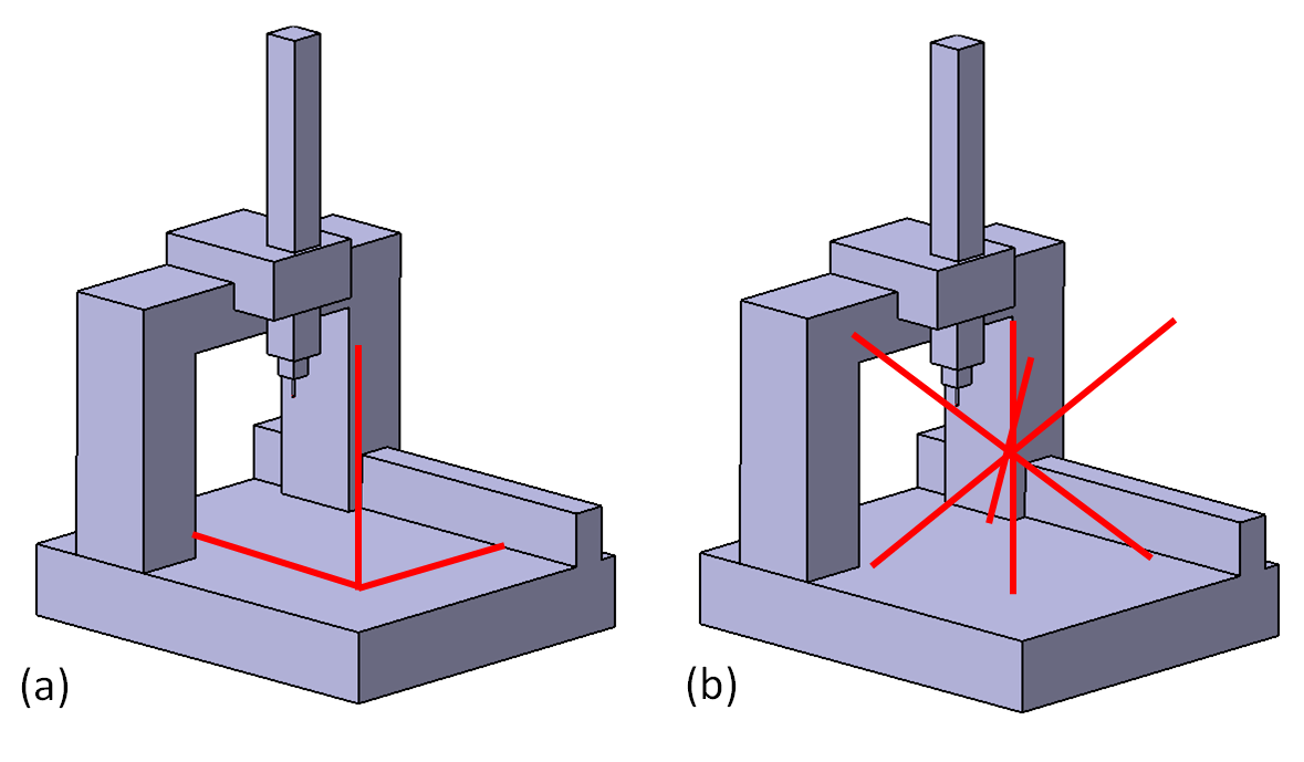
In the world of Coordinate Measuring Machine (CMM) programming, accuracy begins long before a probe touches a part. The foundation of every precise measurement is fixturing. To measure a part accurately and repeatably, a programmer must first understand how to physically and mathematically "lock" that part in space. This process is known as constraining its Degrees of Freedom (DOF).
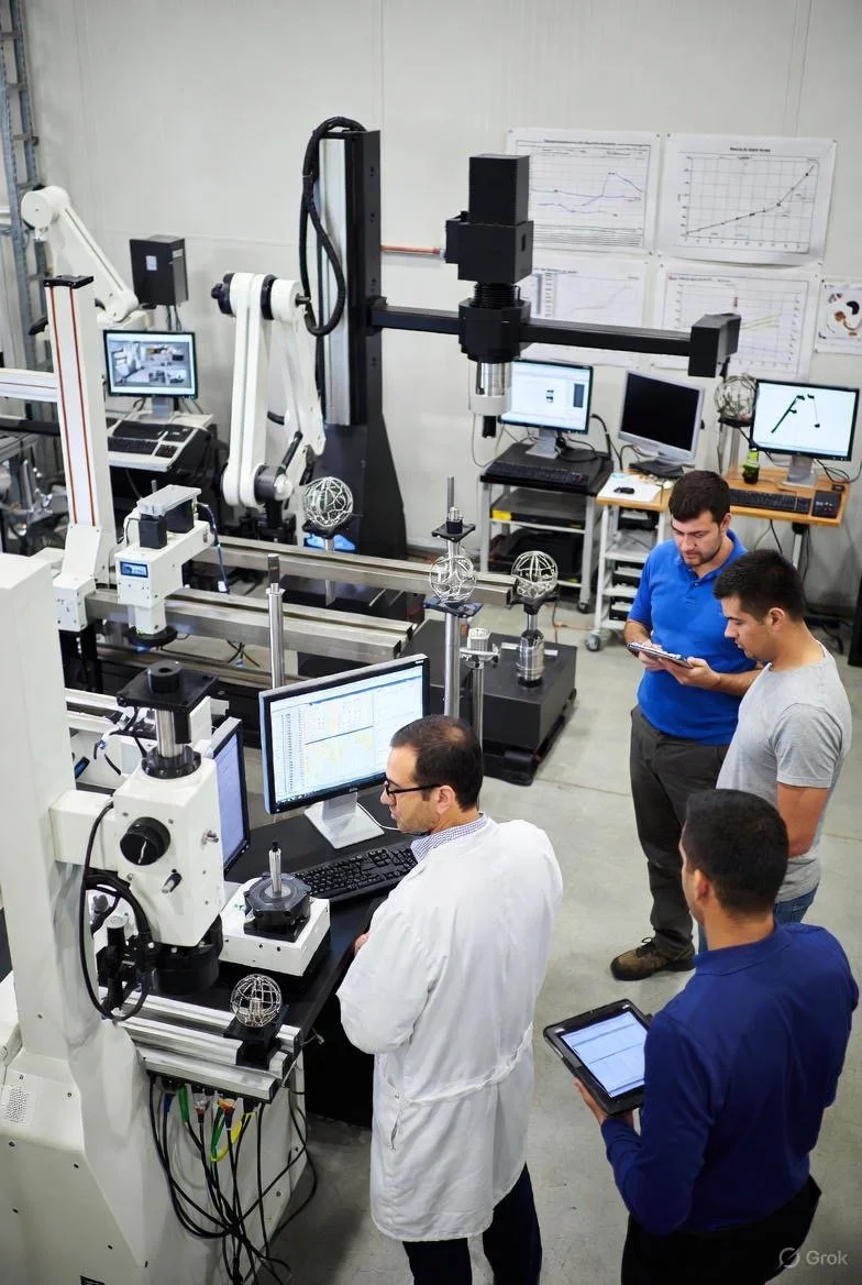
Multisensor Metrology Systems: The Latest Advancements
The technology available to today’s modern manufacturers – allowing them to create complex parts quickly – is better than ever. Advancements in core production and fabrication equipment are seemingly endless.
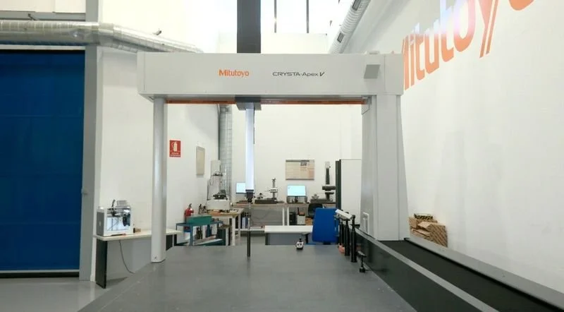
Mitutoyo underscores strategic metrology partnership with Sariki
Metrology company Mitutoyo Japan has reaffirmed its commitment to the European market by selecting Sariki as one of its key strategic partners and sending a high-level delegation to Spain.
Why Invest in User-Friendly 3D Metrology Software
In the fast-paced world of modern manufacturing, the metrology industry faces unprecedented pressures. With global demands for higher production volumes, stricter quality standards, and shorter lead times, metrologists must navigate complex challenges while ensuring precision and efficiency.
Mastering CMM Correlation: A Guide to Validating Upgrades and Avoiding Costly Mistakes
In the ever-evolving field of dimensional metrology, integrating cutting-edge measurement technologies into established quality assurance workflows presents a formidable challenge.
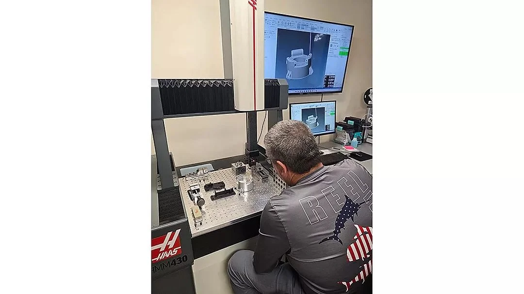
Somebody Always Has to Go First: Grand Traverse Tool Becomes First Haas CMM Customer with Verisurf Software Integration
Traverse City, Michigan, has a long history of “firsts” in American manufacturing. In the 1940s, it was here that the first NC machine tool (Numerically Controlled) was developed to produce complex helicopter blades - an innovation that would forever change the aerospace industry.

How to choose the right 3D measuring system
Metrology has undergone a significant evolution with the advent of 3D measurement and scanning technologies. By 2025, the global 3D scanning market alone is expected to reach $53,345 million, according to Allied Market Research. Indeed, the global manufacturing industry is currently undergoing radical transformations thanks to the harnessing of the capabilities of 3D measurement devices.
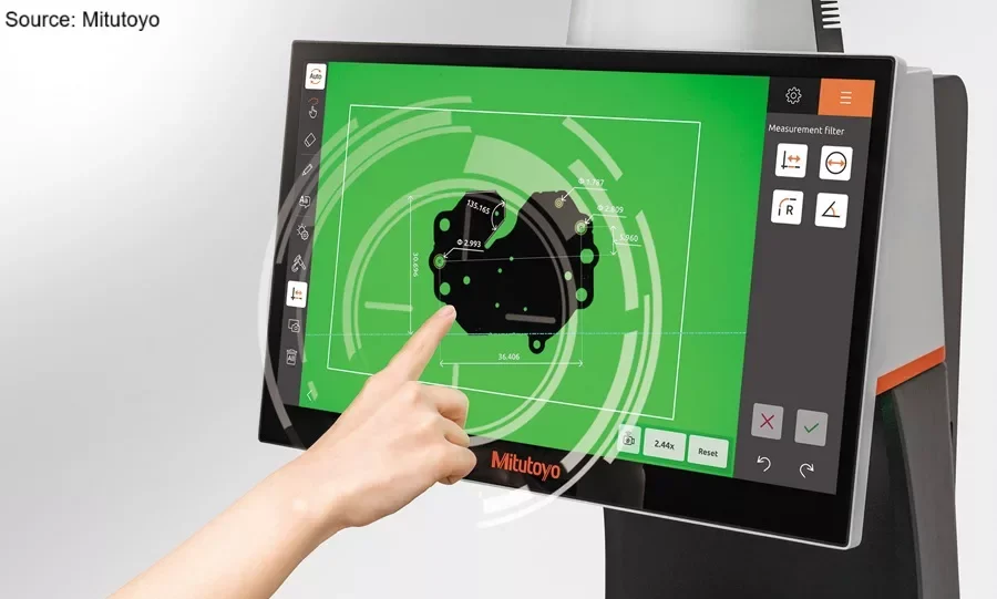
Mitutoyo QM-Fit Measurement System
Mitutoyo America Corporation introduces the QM-Fit Smart Vision System. The QM-Fit represents a step forward in optical metrology. The system features a wide field of view that can intelligently recognize part geometry, allowing measurements to be initiated automatically by extracting shapes displayed on the 15.6-inch intuitive color touchscreen.
CMM Technology on the “Shop Floor”? Why Not!
“The biggest challenge with CMMs is that they are CMMs. They have been in the industry for a very long time and typically have a negative connotation about them. However, because they have been in the industry for so long, they are one of the most accurate, reliable, and cost-effective tools for measuring parts three dimensionally.
The Unbroken Chain of Confidence: Integrating Measurement Traceability, Advanced Uncertainty Management, and Digital Confirmation in CMM Operations
The integrity of dimensional measurement, particularly within the Coordinate Measuring Machine (CMM) discipline, is governed by a stringent framework of international standards designed to ensure comparability, consistency, and absolute confidence in the results.
Anchoring Precision: Advanced Metrological Strategies for Primary Datum Plane Establishment on Coordinate Measuring Machines
The integrity of Geometric Dimensioning and Tolerancing (GD&T) specifications hinges entirely upon the stability and accuracy of the Datum Reference Frame (DRF). As the foundation of this framework, the primary datum plane—typically designated Datum A—serves the critical function of establishing the initial orientation and location of a manufactured component in three-dimensional space.
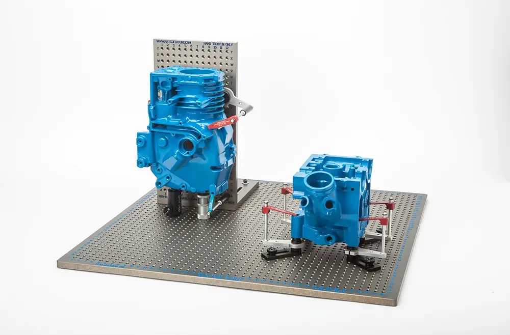
Precision Metrology Fixturing: Principles of Kinematic Design and Non-Deforming Part Clamping for CMM Systems
Coordinate Measuring Machines (CMMs) represent the foundational technology for precision quality control in modern manufacturing, largely replacing traditional, time-intensive methods reliant on single-purpose gauges and inspection fixtures.
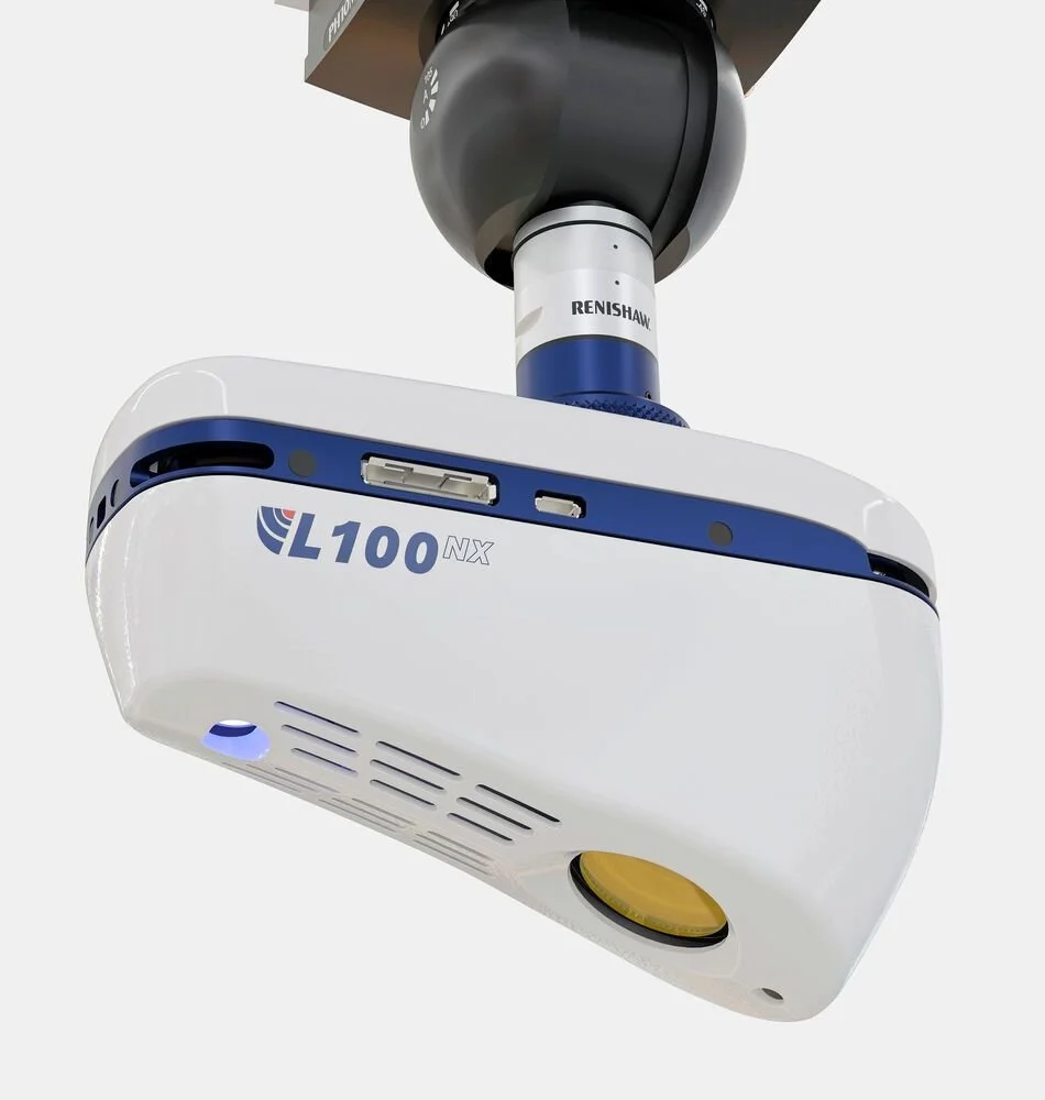
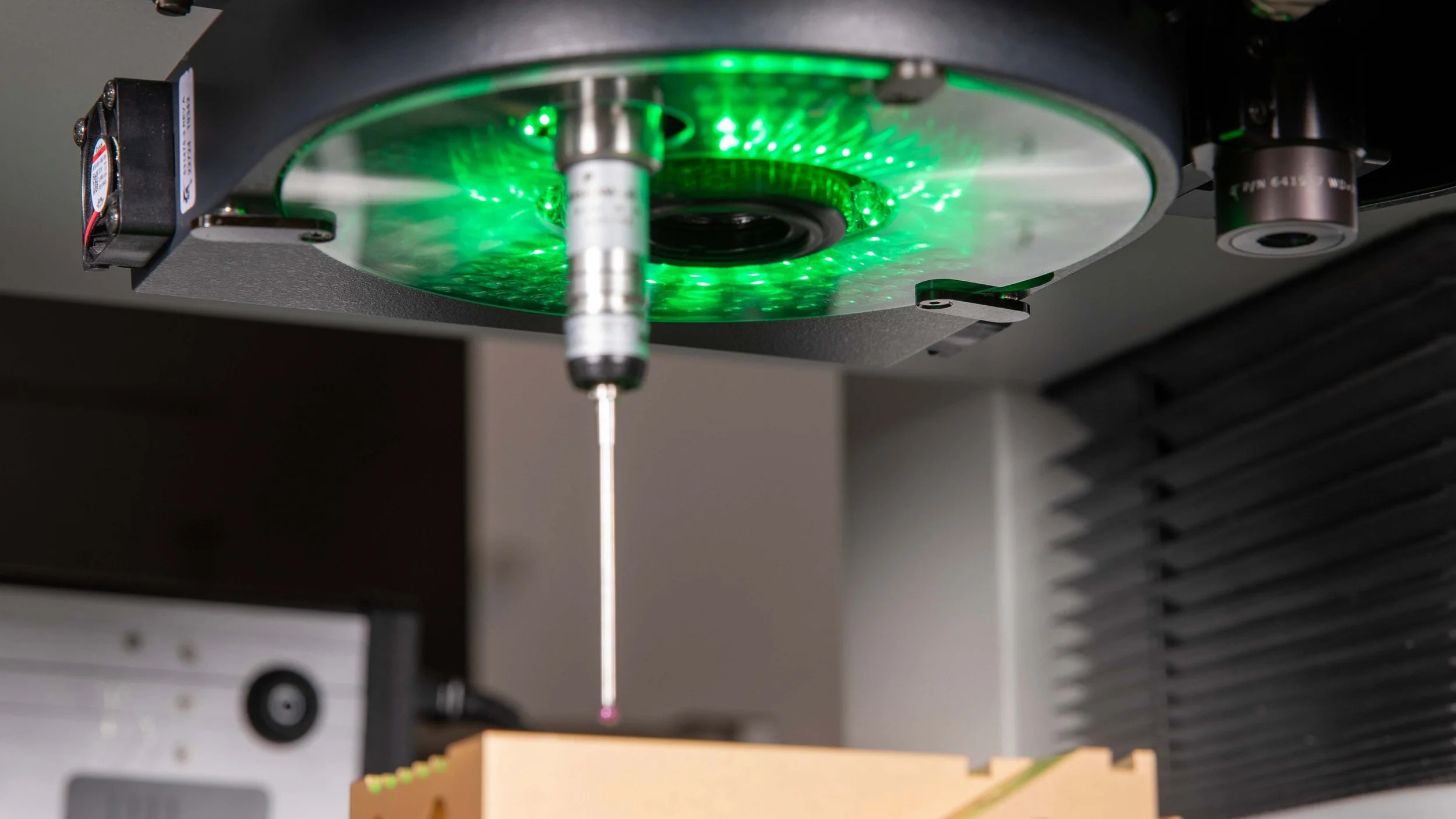
Blue laser technology enhances accuracy in coordinate metrology
LK Metrology has introduced the L100NX, a new blue-laser scanner for coordinate measuring machines that enhances accuracy and data quality in precision inspection. Combining intelligent sensor control with improved usability, the system sets the stage for faster, more reliable measurement of complex components.