
What is Boundary Representation (B-Rep)?
B-Rep, or boundary representation, is a term you will likely come across during any research involving 3D modeling. It is the most popular method used to represent 3D shapes in a computer. Understanding the basics of how B-Rep is useful for those considering developing their own applications that leverage 3D technology, those who use the tools themselves, or anyone involved in industries that do.
Rotating a Part About a Central Axis: Advantages, Limitations, and Alignment Strategy Tradeoffs
Rotating a measured part about a central axis is a common alignment strategy in coordinate metrology, particularly when inspecting rotationally symmetric parts, bolt circles, turbine components, gears, and multi-feature patterns distributed around a datum axis. While the concept is straightforward, the method used to establish the rotation—whether through fixed offsets, equal-distance offsets, or direct angular rotation—can have significant consequences for measurement stability, error distribution, and traceability to the design intent.
Key Differences between ASME and ISO GD&T
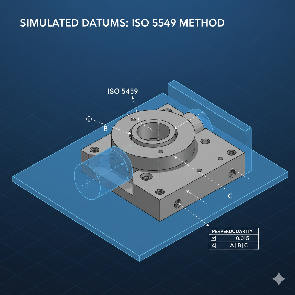
When working with GD&T, it's crucial to understand the fundamental differences between ASME Y14.5 and the ISO GPS standards. While both systems define and communicate tolerances, they differ in their core philosophy and default rules. ASME Y14.5 is a single, comprehensive standard that defaults to the Envelope Principle (Rule #1), meaning form and size are inherently linked. In contrast, the ISO GPS system is a family of interconnected standards, including ISO 5459, that defaults to the Independency Principle, treating size and form as separate unless otherwise specified. This distinction is most apparent in how datums are defined, with ISO 5459 providing a more mathematically rigorous approach to establishing a datum reference frame using a simulated datum.
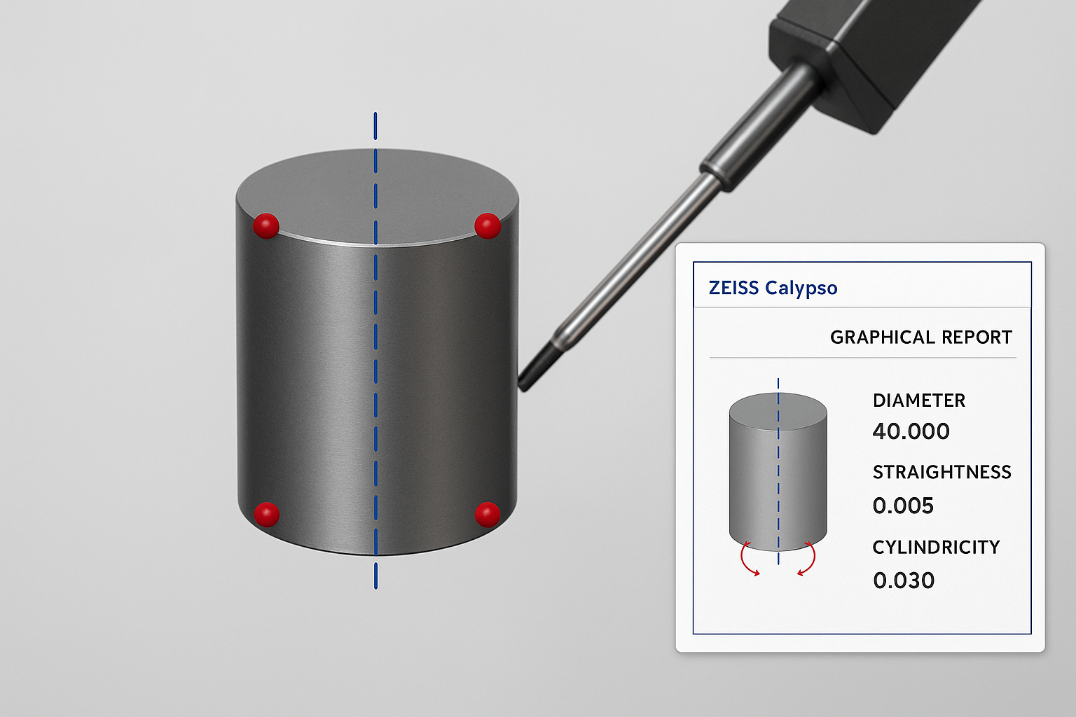
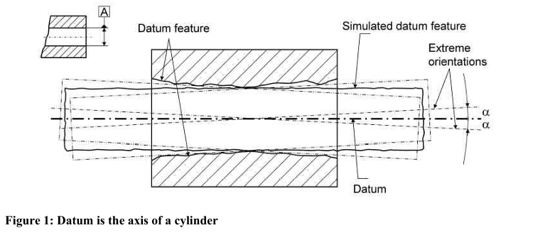
Why a cylinder can be unreliable for spatial alignment
In precision metrology, relying on a full cylinder to define spatial alignment can introduce subtle but significant errors. A fitted cylinder averages all surface deviations, meaning taper, lobing, or localized form errors can tilt or shift the calculated axis. This global best-fit does not always reflect the true functional centerline. In contrast, constructing a 3D line from individual circle sections isolates each cross-section, averages localized imperfections, and produces a more robust datum axis. By understanding how different feature-fitting methods handle form error, CMM programmers can ensure more consistent and functionally accurate measurements — especially in critical alignment operations.
Establishing the Alignment in any CMM Program
In CMM programming, alignment is the process of relating the real-world part to the theoretical coordinate system defined in the drawing or CAD model. It’s like giving the machine a map — without a correct alignment, even perfectly accurate measurements won’t match design intent.
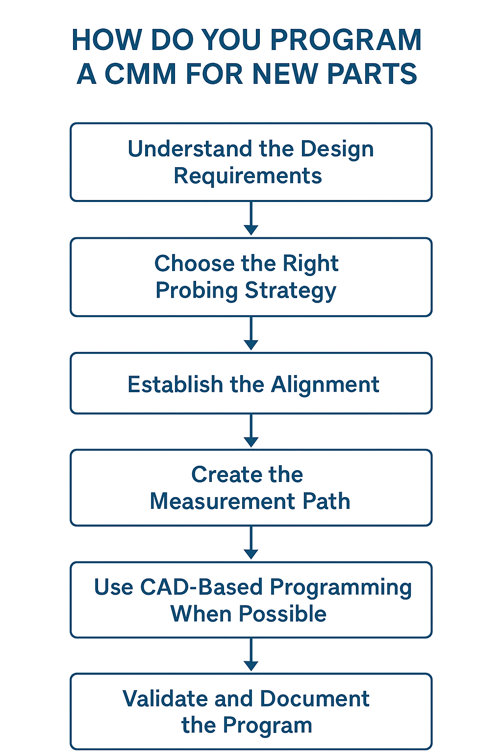
How do you program a CMM for new parts?
Programming a CMM for a new part is about translating the design intent (often in the form of CAD models and engineering drawings) into a measurement routine the machine can execute accurately and consistently.
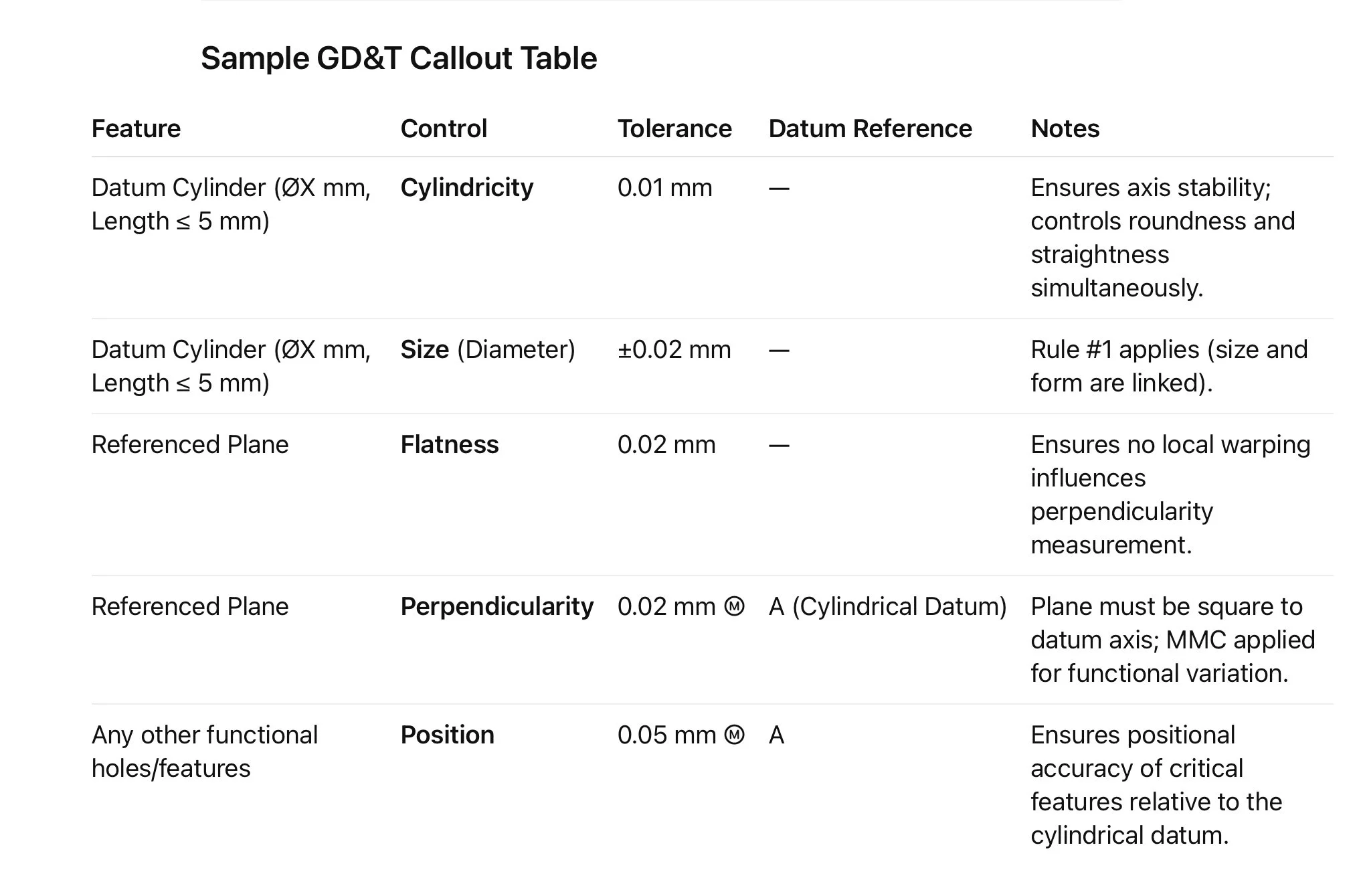
Controlling Perpendicularity of a Plane Using a Short Cylindrical Datum
When inspecting a component where a short cylindrical feature serves as a datum and a plane must be perpendicular to that datum, the strategy requires careful attention to both geometric design and measurement technique. A cylinder with a length of 5 mm or less is inherently more sensitive to measurement variation — and if not supported by additional GD&T, it can yield inconsistent perpendicularity results.
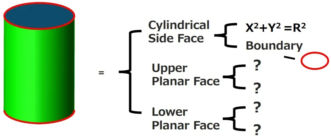
Datum Definition When the Datum Is a Cylinder
When measuring a part with a datum feature requirement that requires you use a cylinder as the spatial orientation datum (base plane datum) there are several considerations you must keep in mind.
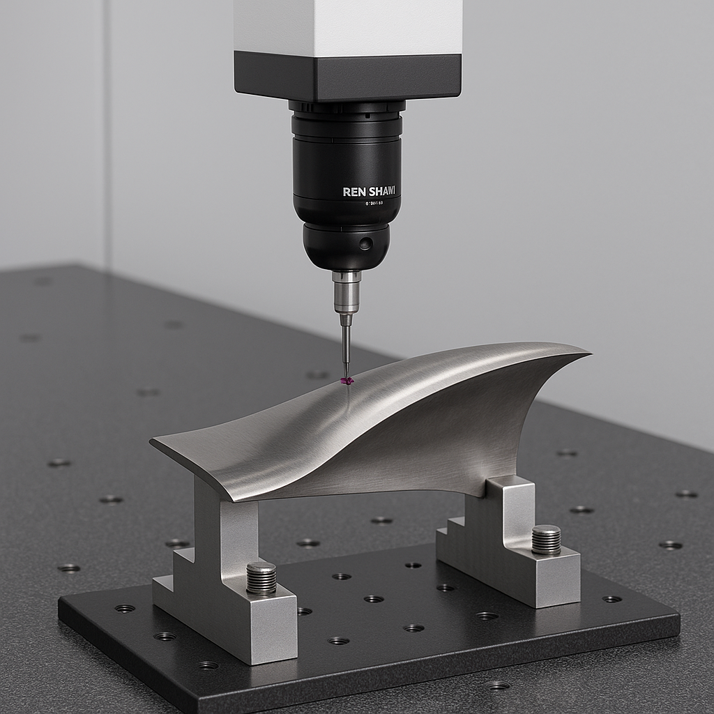
Precision Inspection of Airfoil Blades Using a Coordinate Measuring Machine (CMM)
Airfoil blades, essential components of turbines and jet engines, require extreme precision in their geometry to ensure optimal aerodynamic performance, structural integrity, and energy efficiency. Accurate inspection of airfoils is paramount, and Coordinate Measuring Machines (CMMs) have become the gold standard for achieving this. This article outlines the critical steps, methods, and tools involved in inspecting airfoil blades on a CMM, including alignment, probing strategies, and feature evaluation.
Introduction to GD&T
Geometric Dimensioning & Tolerancing (GD&T) is a symbolic language—standardized by ASME Y14.5 and similar ISO standards—used on engineering drawings and 3D models to precisely communicate allowable geometric variation. It defines the nominal (perfect) geometry of parts and assemblies, as well as their permissible size, form, orientation, and location deviations. GD&T makes design intention explicit, ensuring parts will work together as intended even with slight manufacturing variability
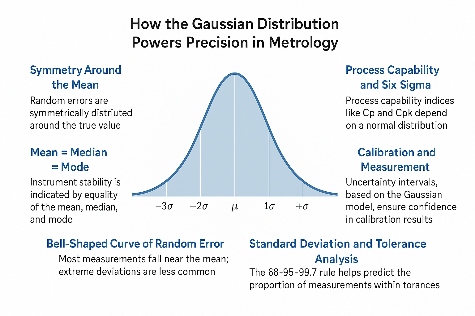
How the Gaussian Distribution Powers Precision in Metrology
How the Gaussian Distribution Powers Precision in Metrology
Simultaneous Requirements in GD&T: What They Are & How They Work
Geometric Dimensioning & Tolerancing (GD&T) uses symbolic language to control geometric relationships. A simultaneous requirement means multiple features must meet their geometric controls together—in the same setup and referencing the same datums in the same order and material condition.

ISO 14405-1:2016 Circular Options
Within the ISO 14405-1 are options which will be applied to circular features. These will be indicated on the print.

Good Measurement Practice for Ensuring Metrological Traceability
Good Measurement Practice for Ensuring Metrological Traceability

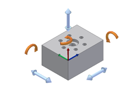
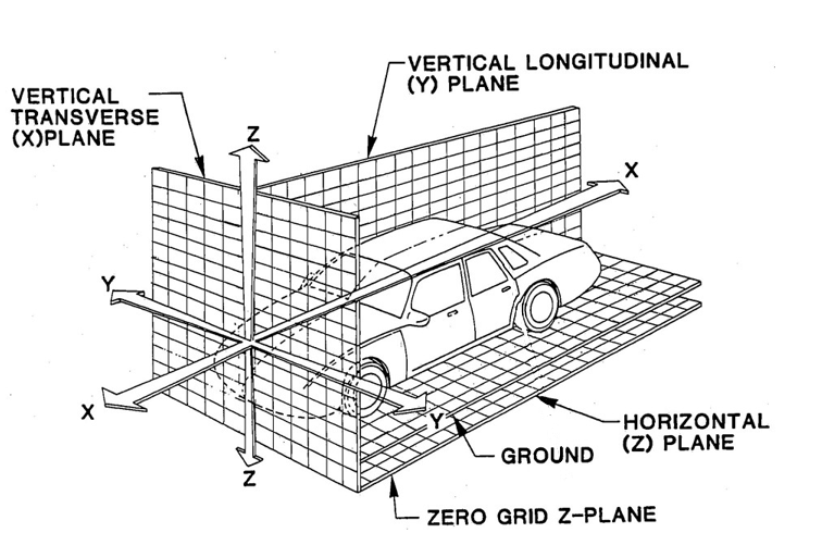
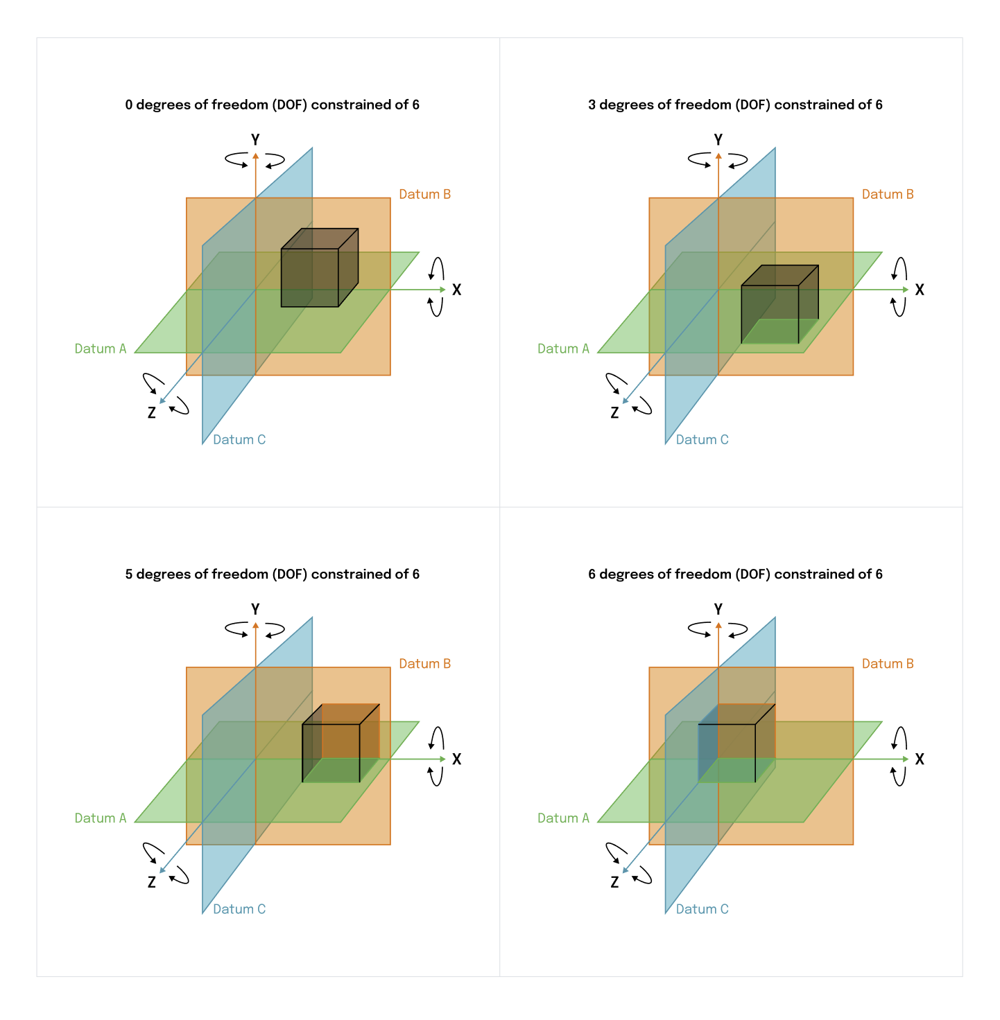
Understanding the 6 Degrees of Freedom (Copy)
Understanding the principle of the 6 degrees of freedom is essential to aligning your part correctly on the Coordinate Measuring Machine (CMM). When a part is placed on the CMM the location of the part is not known. It must be defined by using several features known as datums.