DMIS Probe Command Set
DMIS uses the Sensor Definition code (SNSDEF) This defines a probe sensor used by the dimensional measuring equipment (DME) in making measurements, and assigns to it a label name
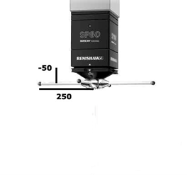
Below is the command set for a FIXED head probe
S(TIP1)=SNSDEF/PROBE,FIXED,CART,250,0,-50,0,0,1,3
The fixed head systems use the Cartesian (or rectangular) coordinates. In the above example the center of the stylus is 250mm in the X axis, 0mm in the Y axis, and –50mm in the Z axis. These measurements come from the bottom of the quill and the center of the probe assembly to the center of the ball stylus. The 0,0,1 are the vector direction of the mounted probe. These values show the probe is mounted in the Z axis as opposed to a horizontal machine where the vector would be 1,0,0. The 3 at the end of the statement is the diameter of the stylus ball.
Below is the command set for a standard rotating probe head
S(TIP1)=SNSDEF/PROBE,INDEX,POL,90,45,0,0,1,127,2
Below is the command set for a rotating (INDEX) head probe
S(TIP1)=SNSDEF/PROBE,INDEX,POL,45,45,0,0,1,100,3
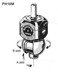
The indexing or articulating probe heads are defined by Polar coordinates. The indexing head angles are referred to as their A B angles.
A = the rotation of the probe in the lift direction
B = the rotation of the probe around the heads mounting axis
In the above example the probe is rotated 45 degrees in the A or lift angle and rotated 45 degrees in the B angle or about the mounted probe axis. The mounted probe vector angle is 0,0,1. The 100 dimension refers to the linear length from the center of the rotating sphere of the probe to the center of the stylus ball. The 3 represents the size of the stylus ball, 3mm


