CMM Manager: Slot with MMC
Mark Boucher

The method is the same whether you are creating a slot that is open or closed.
Create the CMM Alignment.
Measure Plane1 – Define the plane parameters as desired. Here we are probing 6 points.

Measure Plane2 – Define the plane parameters as desired. Here we are probing 6 points

Under the Features Tab select the Construction: Point icon. Now create the Centroid Point of Plane1 and Plane2. These points were named Plane1_Centroid and Plane2_Centroid.
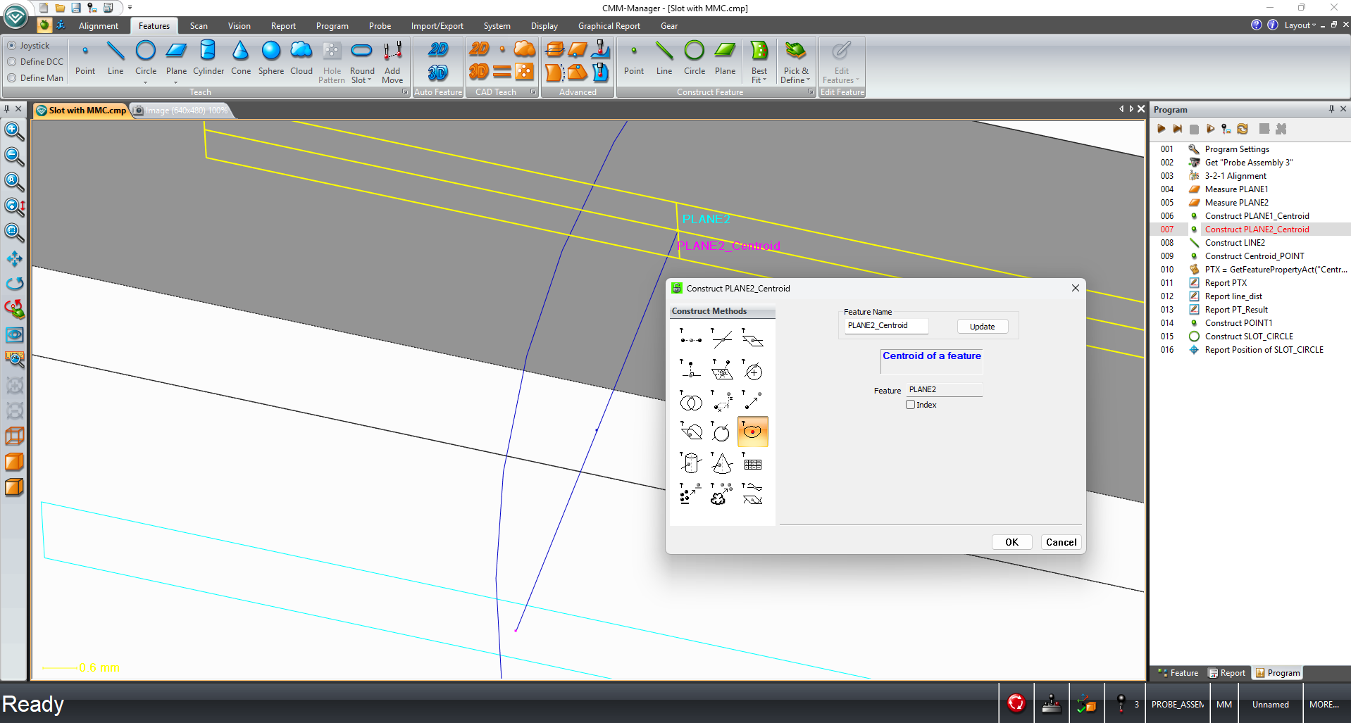
Now create a Line using the plane centroid points. Construction: Line

Now we must create the centroid point of the line. Drag Line2 into the Feature input. This will become the center point of our circle that will be used to determine the MMC calculation. Name this feature Centroid_POINT.

Now we will add the VB Script
Open the Programming Tab and select VB Script.
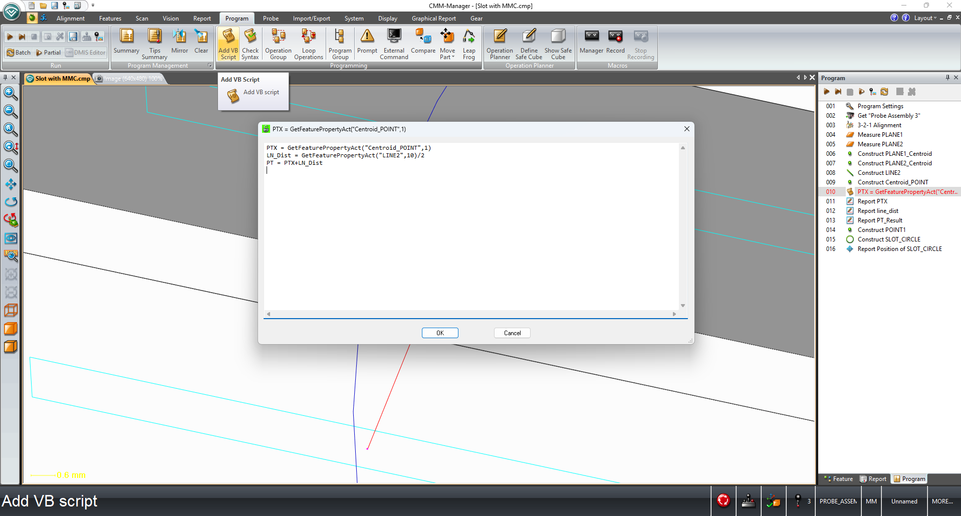
Enter the following code:
PTX = GetFeaturePropertyAct("Centroid_POINT",1)
LN_Dist = GetFeaturePropertyAct("LINE2",10)/2
PT = PTX+LN_Dist
PTX is the location of the line’s centroid point. Right now, we have 3 points in our program the centroid of each plane and the centroid of the line. They are in a straight line, and we won’t be able to create a circle with the points in a line. So, we will take the line distance and divide it in half. Then we will take that point and offset it to create the circle.
LN_Dist is the line divided in half.

PT is the formula to create the point in the X direction. Take the X value of the centroid point of the line and add half the line distance.
Open a Constructed Point and select the Define Point option. Click Set Variables and enter PT in the X value.
Click OK. In the Y and Z values enter the blueprint values for the center of the slot.

Now we will create the slot circle to use for the position of the slot with MMC.
Construct a Circle with three points. Enter the Plane1_Centroid point, the Plane2_Centroid point, and the newly created Point1.

Here you may run into a graphical issue. Your circle may not be in the center of the slot and too large.
The VB Script will not be updated without running the program. It will correct itself when the program is run.

Now add the Positional Callout. Enter Circle1, the constructed circle.
Be sure to edit the Feature Report tab to enter the correct blueprint values for the center of the slot and slot width (this will be the diameter input).

Now when the program is run the diameter will show in the correct position with the positional callout at MMC.

YouTube video link for this video https://youtu.be/eGzqJfa4WQg
To better understand VB Scripting see the book below.