Basic CMM Alignments
We will cover the most commonly used datum alignments used in the CMM world. The following is an excerpt from the Calypso Basic Training Manual from CMM Quarterly.
Alignment terms you to be familiar with:
Primary Datum– The datum feature that first situates the part within the datum reference frame. The primary datum is the first feature to contact a fixture or surface during assembly. In addition to a plane this may also be a cylinder, sphere, or cone. This is used to spatial align the part to the CMM axis.
Secondary Datum– the alignment plane of the 3-2-1 method. This feature is used to rotate the part to match a CMM axis. A secondary datum may be a line, circle, plane, or 3d-line.
Tertiary Datum- the datum feature that situates the part within the datum reference frame after the secondary datum. This feature sets the origin of the par
What is a Coordinate System?
One of the first things that you must do in creating a part program is to create a coordinate system on the part. This locates all subsequent measurements back to this location. How do I know where to create this coordinate system on my part? The location of the coordinate system needs to be the same as on the blueprint. The blueprint will indicate where the engineer wants the measurements to be taken from. This is usually determined by how the part is assembled or its relationship to the other parts in the assembly.
A coordinate system is the ‘you are here’ indicator on a map and how far it is to the next feature is the linear dimension. Linear dimensioning is the method of locating a feature. In order to know the exact number to this feature you must have a start point and that is the coordinate system.
Creating an Alignment System
Let’s begin to measure some features and create alignments. We will cover some of the basic alignments. Use the joystick and feature recognition to create the features. We will then create a new base alignment to locate the part to the CMM and constrain all degrees of freedom.
Place the test part on the CMM. The practice alignments in this section will use the test part shown at the beginning of this section. If you choose to use your own part that is fine just use the same concepts to create the alignment. If you have machined this test part use this part first and then practice these alignments on your own part. We will not execute any program yet so manually measuring these features on another part can be done without fear of breaking a stylus.
Make sure you have a calibrated stylus loaded.
Let’s begin
Plane/ Circle/ Line
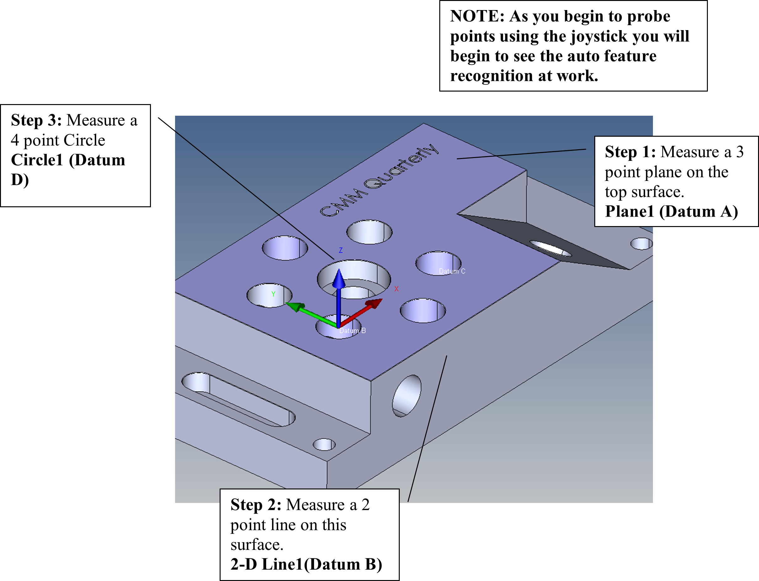
When creating an alignment system in our examples the alignment features must be measured first (You may open the Base Alignment window first and measure the features as you go). These features are then called into the alignment function. In this example we probed a plane, 2-D line, and a circle.
Select Base/ Start Alignment on the Measurement Plan panel.

Begin to select the features that will make up the alignment. By selecting the empty square to the left of the item.

Spatial or Rotation in Space
Pick the plane as the spatial orientation or rotation in space and set Z origin. This will constrain 3 degrees of freedom.
Next pick the line as the Planar Rotation.

Planar Rotation
This will mathematically align the part, in this example, along the CMM X Axis
This will constrain 1 degree of freedom.
Now pick the circle as the X and Y origin. This constrains the last 2 degrees of freedom.

Origin
The coordinate system symbol (trihedren) will now move to indicate the programs origin.
The alignment will be on the top plane center in X to Circle1 and the origin in Y on the line.

Plane/ Circle/ Circle
Another common alignment is the plane, circle, circle alignment.

Measure the plane and the circles for the alignment. Now click Base Alignment on the Resources pane.
Select Create New Base Alignment.

Spatial or Rotation in Space
Pick the plane as the Spatial Orientation and set the Z Origin to this plane
This will level the part to the CMM Z axis.

Origin
Enter Circle1 as the X and the Y Origin
Finally choose Circle2 as the Planar Rotation

Planar Rotation
Notice: The planar rotation axis is +X.
This will rotate the measured hole to be in-line with Circle1. It is very important to select the correct alignment axis to create the proper alignment.
This will rotate the alignment so the two circles are in line

The alignment on the plane zeroed at Circle 1 and aligned to Circle 2

Plane/ Line/ Line

Another common alignment is the plane, line, line alignment.
Measure the plane and the lines for the alignment. Now click Base Alignment on the Measurement Plan pane.
Measure Line 1 along the X axis and Line 2 along the Y axis
Select Create New Base Alignment.

Spatial or Rotation in Space
Enter the plane as the Spatial Orientation and set the Z origin on the plane.
This will level the part to the CMM Z axis and constrain 3 degrees of freedom.
Select Datum B as the Planar Rotation and set to +X also this will be our Y Origin.
This will constrain 2 degrees of freedom.
Select Datum C as the X Origin. This will constrain the last degree of freedom.

The result will be a fully constrained part alignment.


Plane/ Line/ Point
Plane — Probe 3 or more points on the top surface to level the part to the CMM axis. 3 points are the minimum required for a plane. Rename this plane as Datum A. Set the Spatial Orientation, to this plane. This will level or square the plane to the CMM even if your part when placed on the CMM visually not square to the CMM. The software will compensate and square the plane. In our example this is the Z axis, set the Z zero, origin, to this plane. This constrains 3 degrees of freedom.
Line — Probe a line down the X axis of the part. This will allow you to rotate this line to the axis of the CMM. It will force the line to be normal to the CMM axis even if visually it is not. In our example, the line is along the X axis so you would set the alignment axis, or Planar Rotation, about Z the axis and align the X axis. The part will rotate about Z and align X. Set the Y origin on this line. Why the Y? Although the line moves along the X axis the Y origin is set to constrain the movement in Y. Measurements from this surface to a feature are along the Y axis. X will be set on the next line. This constrains 2 degrees of freedom.
Point — Probe a point on the remaining axis and set the X origin on this point. This constrains the last remaining degree of freedom.


Plane/ Circle/ Line
Plane — Probe 3 or more points on the top surface to level the part to the CMM axis. 3 points are the minimum required for a plane. Rename Datum A. Set the Spatial Orientation, to this plane. This will level or square the plane to the CMM even if your part when placed on the CMM visually not square to the CMM. The software will compensate and square the plane. In our example this is the Z axis, set the Z zero, origin, to this plane. This constrains 3 degrees of freedom.
Circle — Probe a circle using 3 points or more to define an origin. In this example we probe the large diameter in the middle of the bolt pattern and set our X & Y origin to the circle. Rename as Datum B. This will move the origin to the center of this circle. Setting the X & Y origin here constrains 2 degrees of freedom.
Line — Probe a line down the X axis of the part. Rename as Datum C. This will allow you to rotate about the circle to align to the axis of the CMM. It will force the line to be normal to the CMM axis even if visually it is not. In our example, the line is along the X axis so you would set the alignment axis, or Planar Rotation, about Z the axis and align the X axis. The part will rotate about Z and align X. This constrains the last degree of freedom.


Plane/ Circle/ Circle Offset

We will create an alignment off-setting by the nominal value on the blueprint.
The offset between the two diameters is 866” in the X axis and .500” in the Y axis. We will use these values to offset the alignment.
Follow the steps above and create the plane and two circle features.
Open the Base / Start Alignment window from the Resource panel
Select the plane for the Spatial Rotation and the Z origin, Datum B for the X, Y Origin and Offset Circle for the Planar Rotation. When you select the Offset Circle a window may appear inquiring which axis will be aligned, choose +X.
Selecting Offset Circle will rotate the trihedrin to align the two circles. This would be acceptable if want them to be in line but we want to offset to the blueprint nominal.

Selecting Offset Circle will rotate the trihedrin to align the two circles. This would be acceptable if want them to be in line but we want to offset to the blueprint nominal.
Click on the Special button and this will open rotation options.
Enter 0.500 in the Rotate to Distance to rotate to one axis.

Special
this function allows you to rotate or offset any alignment
Or you may also rotate by equal distance (entering both .866 and .500) to equally displace any machining variation in each axis.
Rotating by an angle is the other option. Rotate by an Angle allows any error to be forced equally along the axes.

Additional Alignments within a program
To create additional alignments, go to Resources/ Utilities/ Alignment
You can create additional alignments you need within your program with this command. You will notice at the top on this dialog box that this new alignment will be built upon another alignment. This default is the base alignment but you may choose to build the new alignment on any that you select.
For example: This allows you to use a complex alignment that you have built, i.e., Alignment1, and build Alignment2 off of this Alignment1 but only move the X and Y origin to another feature. The complex alignment scheme does not need to be rebuilt but only selected as the alignment to be built upon.

Alignment and Datum Reference Frames
Alignment
It is a three dimensional coordinate system that constrains all six degrees of freedom and is the basis of travel commands of the CMM.
The base alignment is a part alignment that defines the position of the workpiece on the CMM. There is only one base alignment in every measurement plan.
Datum Reference Frame (DRF)
It is a Frame of Reference that is used for evaluation of measurements from the CMM as specified by the blueprint.
The Difference
Alignments are intended only for machine control.
DRF’s are intended only for Characteristic evaluations.
Any of the location, orientation and distance characteristics can use a DRF. i.e. Profile, True Position, Cartesian Distance, etc…

As you can see in the above print the diameters in the bolt circle are toleranced back to datum D.
If you use the base alignment in the true position too many constraints are applied.
When applying true position back to the base alignment (-A-, -B-, -C-) is incorrect, instead you must apply true position using Datums –A-, and –D-. This allows the tolerance to move about diameter D. MMC will not be allowed with alignments only with a DRF.
Description
Master the foundation of precision measurement.
This book is a complete guide to understanding, applying, and mastering datums and datum alignments on CMMs (Coordinate Measuring Machines). Written by Mark Boucher, founder of CMM Quarterly, it distills decades of metrology expertise into clear, practical chapters designed for engineers, machinists, quality professionals, and students of GD&T.
From the basics of datum reference frames to advanced strategies like iterative and best-fit alignments, this book explains not just the how but also the why behind CMM alignment practices. Each chapter blends theory, industry standards (ISO/ASME), and real-world application with best practices, diagrams, and examples that can be applied immediately on the shop floor or in the lab.
What You’ll Learn
The fundamentals of datums and datum reference frames (DRFs).
Manual, CAD-based, best-fit, and iterative alignment strategies.
How fixturing and workholding affect measurement accuracy.
Managing measurement uncertainty and its impact on datum selection.
Troubleshooting alignment issues and preventing common errors.
Communication and reporting practices that build trust across teams.
Why This Book Matters
Accurate measurement starts with accurate alignment. Misapplied datums can lead to costly scrap, disputes with customers, and unreliable inspection results. This book gives you the knowledge and tools to confidently control datums, stabilize measurements, and produce results that stand up to scrutiny.
Who Should Purchase the Book
CMM programmers and operators.
Quality engineers and inspectors.
Design engineers working with GD&T.
Machinists and manufacturing leaders seeking better alignment practices.
Students and professionals looking to strengthen their metrology foundation.
Format: Digital Download
CMM Quarterly Publications offers the Calypso Basic training manual. This CMM training package includes a training manual. Online hours are available at additional costs.
This manual covers both non-Cad and CAD programming.
This is a digital copy of the Calypso Basic Training Manual. Upon purchase the videos that accompany the handbook will be sent by a large file server service to your email to download.
This product is published by CMM Quarterly, the leader in cmm training products.