

TrackScan Sharp Series Optical 3D Scanning System
The TrackScan Sharp series is a cutting-edge optical 3D scanning system, engineered with 25-megapixel industrial cameras and advanced onboard processors for edge computing. This system is specifically designed to measure large-scale parts over long distances with remarkable speed and precision.
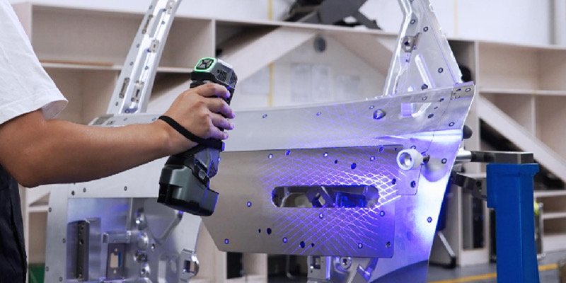
Intelligent, Wireless and Palm-Sized 3D Scanner SIMSCAN-E
The SIMSCAN-E is an intelligent, wireless, palm-sized 3D scanner that blends lightweight design with top-tier performance. With advanced wireless scanning technology, it sets a new standard for portable and wireless 3D scanning.
The SIMSCAN-E offers significant benefits by leveraging advanced edge computing and high-definition industrial cameras to deliver exceptional precision and efficiency in capturing 3D data. With the ability to measure up to 6.3 million points per second,it is deal for industries that demand high-performance scanning solutions.
Alignment with Offset Plane
The offset plane can be used in an alignment construction. A good example of an offset plane is cast datum points, where they are rarely on the same plane.