
Key Differences between ASME and ISO GD&T
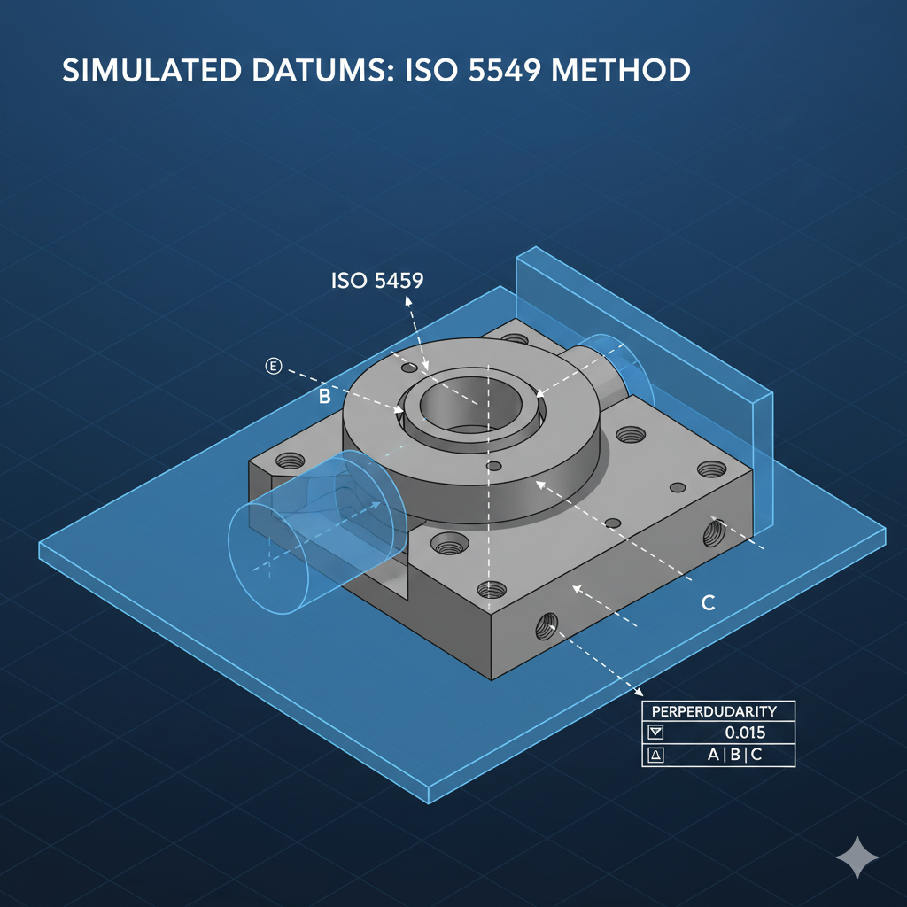
When working with GD&T, it's crucial to understand the fundamental differences between ASME Y14.5 and the ISO GPS standards. While both systems define and communicate tolerances, they differ in their core philosophy and default rules. ASME Y14.5 is a single, comprehensive standard that defaults to the Envelope Principle (Rule #1), meaning form and size are inherently linked. In contrast, the ISO GPS system is a family of interconnected standards, including ISO 5459, that defaults to the Independency Principle, treating size and form as separate unless otherwise specified. This distinction is most apparent in how datums are defined, with ISO 5459 providing a more mathematically rigorous approach to establishing a datum reference frame using a simulated datum.
Why a cylinder can be unreliable for spatial alignment
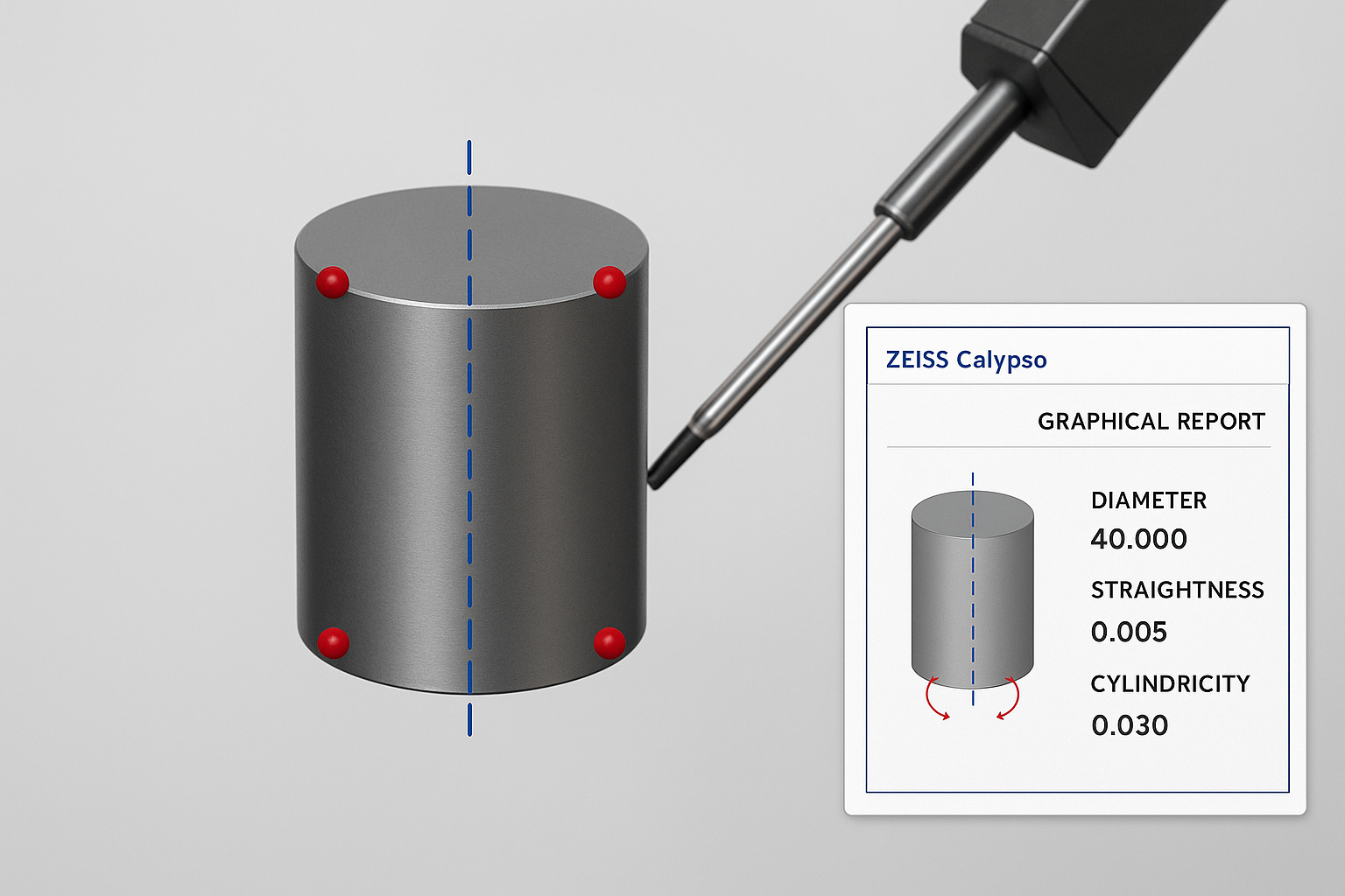
In precision metrology, relying on a full cylinder to define spatial alignment can introduce subtle but significant errors. A fitted cylinder averages all surface deviations, meaning taper, lobing, or localized form errors can tilt or shift the calculated axis. This global best-fit does not always reflect the true functional centerline. In contrast, constructing a 3D line from individual circle sections isolates each cross-section, averages localized imperfections, and produces a more robust datum axis. By understanding how different feature-fitting methods handle form error, CMM programmers can ensure more consistent and functionally accurate measurements — especially in critical alignment operations.
Controlling Perpendicularity of a Plane Using a Short Cylindrical Datum
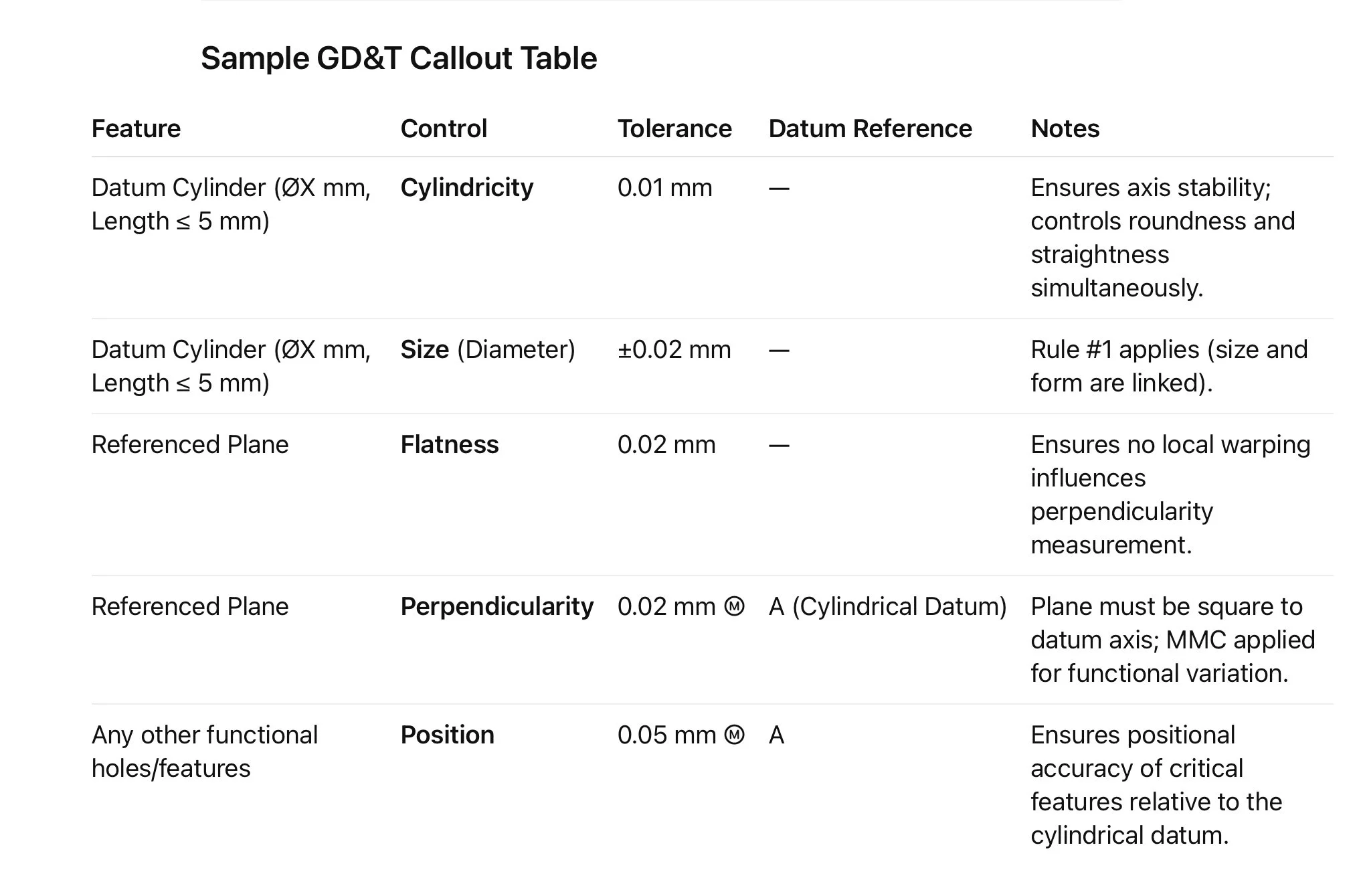
When inspecting a component where a short cylindrical feature serves as a datum and a plane must be perpendicular to that datum, the strategy requires careful attention to both geometric design and measurement technique. A cylinder with a length of 5 mm or less is inherently more sensitive to measurement variation — and if not supported by additional GD&T, it can yield inconsistent perpendicularity results.
Introduction to GD&T
Geometric Dimensioning & Tolerancing (GD&T) is a symbolic language—standardized by ASME Y14.5 and similar ISO standards—used on engineering drawings and 3D models to precisely communicate allowable geometric variation. It defines the nominal (perfect) geometry of parts and assemblies, as well as their permissible size, form, orientation, and location deviations. GD&T makes design intention explicit, ensuring parts will work together as intended even with slight manufacturing variability
Simultaneous Requirements in GD&T: What They Are & How They Work
Geometric Dimensioning & Tolerancing (GD&T) uses symbolic language to control geometric relationships. A simultaneous requirement means multiple features must meet their geometric controls together—in the same setup and referencing the same datums in the same order and material condition.