Creating a 6 Circle Hole Pattern with Variable Size
An excerpt from the Learn How to Use VB Script in CMM Manager Book - Link is here
Objective: We need to measure a 6 circle hole pattern but the machine shop is still testing some parameters so the hole pattern center will be the same but they will cut the pattern radial distance from the center larger and larger until they get the part correct. So, this script will prompt the operator to enter the radial distance from the center and which rotational pattern the holes were measured (clockwise or counterclockwise).

Alignment
Set the alignment as required on the blueprint.

Center of Pattern
Measure the center of the pattern and set the origin to this feature. Save the alignment as “Pattern” to easily recall it.

Measure the Pattern of Holes
Measure the 6 holes, either counterclockwise or clockwise. You will be given, in the VB Script, an option to select which direction you measured.
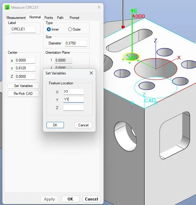
Enter Nominal Feature Variables
In the Nominal tab select Set Variables and enter for Circle1 X1 and Y1, Circle2 - X2, Y2, Circle3 - X3, Y3 and so on for each feature.

Enter the Report Variables
In the Feature Report tab select Set Variables and enter for Circle1 X1 and Y1, Circle2 - X2, Y2, Circle3 - X3, Y3 and so on for each feature.

Enter the VB Script
Above the measured features add the VB Script shown below
VB Script
'---------------------------------------------
' CMM-Manager VB Script
' 6-Hole Bolt Circle with Rotation Option
' Fixed center at (X0,Y0), operator enters radius
'---------------------------------------------
' ---- Known center of pattern ----
centerX = 0 ' Replace with your actual X0
centerY = 0 ' Replace with your actual Y0
' ---- Operator Inputs ----
respR = InputBox("Enter bolt circle radius (Enter Value in Current Units):", "Radius")
rotationDir = InputBox("Enter rotation direction: C for clockwise, CC for counterclockwise", "Rotation", "CC")
If IsNumeric(respR) Then
radialDist = CDbl(respR)
' ---- Config ----
numCircles = 6
startAngleDeg = 90 ' first hole at 12 o'clock
' ---- Math helpers ----
PI = 4 * Atn(1)
stepDeg = 360 / numCircles
' Reverse step for clockwise
If UCase(rotationDir) = "C" Then
stepDeg = -stepDeg
End If
' Named scalars for nominal X/Y
Dim X1,Y1,X2,Y2,X3,Y3,X4,Y4,X5,Y5,X6,Y6
For i = 0 To numCircles-1
angleDeg = startAngleDeg + stepDeg * i
angleRad = angleDeg * PI / 180
x = centerX + radialDist * Cos(angleRad)
y = centerY + radialDist * Sin(angleRad)
Select Case i
Case 0: X1 = x: Y1 = y
Case 1: X2 = x: Y2 = y
Case 2: X3 = x: Y3 = y
Case 3: X4 = x: Y4 = y
Case 4: X5 = x: Y5 = y
Case 5: X6 = x: Y6 = y
End Select
Next
' ---- Optional summary for verification ----
BoltCircleSummary = _
"Bolt Circle R=" & radialDist & " C=(" & centerX & "," & centerY & ") Rotation=" & UCase(rotationDir) & vbCrLf & _
"1: X=" & Round(X1,4) & " Y=" & Round(Y1,4) & vbCrLf & _
"2: X=" & Round(X2,4) & " Y=" & Round(Y2,4) & vbCrLf & _
"3: X=" & Round(X3,4) & " Y=" & Round(Y3,4) & vbCrLf & _
"4: X=" & Round(X4,4) & " Y=" & Round(Y4,4) & vbCrLf & _
"5: X=" & Round(X5,4) & " Y=" & Round(Y5,4) & vbCrLf & _
"6: X=" & Round(X6,4) & " Y=" & Round(Y6,4)
MsgBox BoltCircleSummary
End If
ALTERNATIVE TO USING A CENTER FEATURE
---- Known center of pattern ----
centerX = 0 ' Replace with your actual X0
centerY = 0 ' Replace with your actual Y0
Change the 0 location to your location from the part alignment or different alignment.

Make the Right Choice
You have choices. Make the right choice.