
You have choices, make the right choice
How GD&T Improves Manufacturing Efficiency and Reduces Costs
Geometric Dimensioning and Tolerancing (GD&T) has transformed the way manufacturers communicate design intent and product specifications.

The Ultimate Guide to ASME Y14.5: Understanding, Applying, and Scaling GD&T in Modern Engineering
If you design, manufacture, or inspect physical products, you live with variation. Metals spring back, plastics shrink, heat distorts parts, cutters wear, fixtures deflect, and nobody machines a perfectly straight line or a perfectly round hole. The question is never “does variation exist?,” it’s “how much variation can we allow and still guarantee function?”
Understanding ASME Y14.5.1: Mathematical Definitions of Geometric Dimensioning and Tolerancing
In the precision-driven world of metrology, where Coordinate Measuring Machines (CMMs) and advanced inspection technologies ensure parts meet exacting standards, Geometric Dimensioning and Tolerancing (GD&T) serves as the universal language for defining and communicating engineering tolerances.
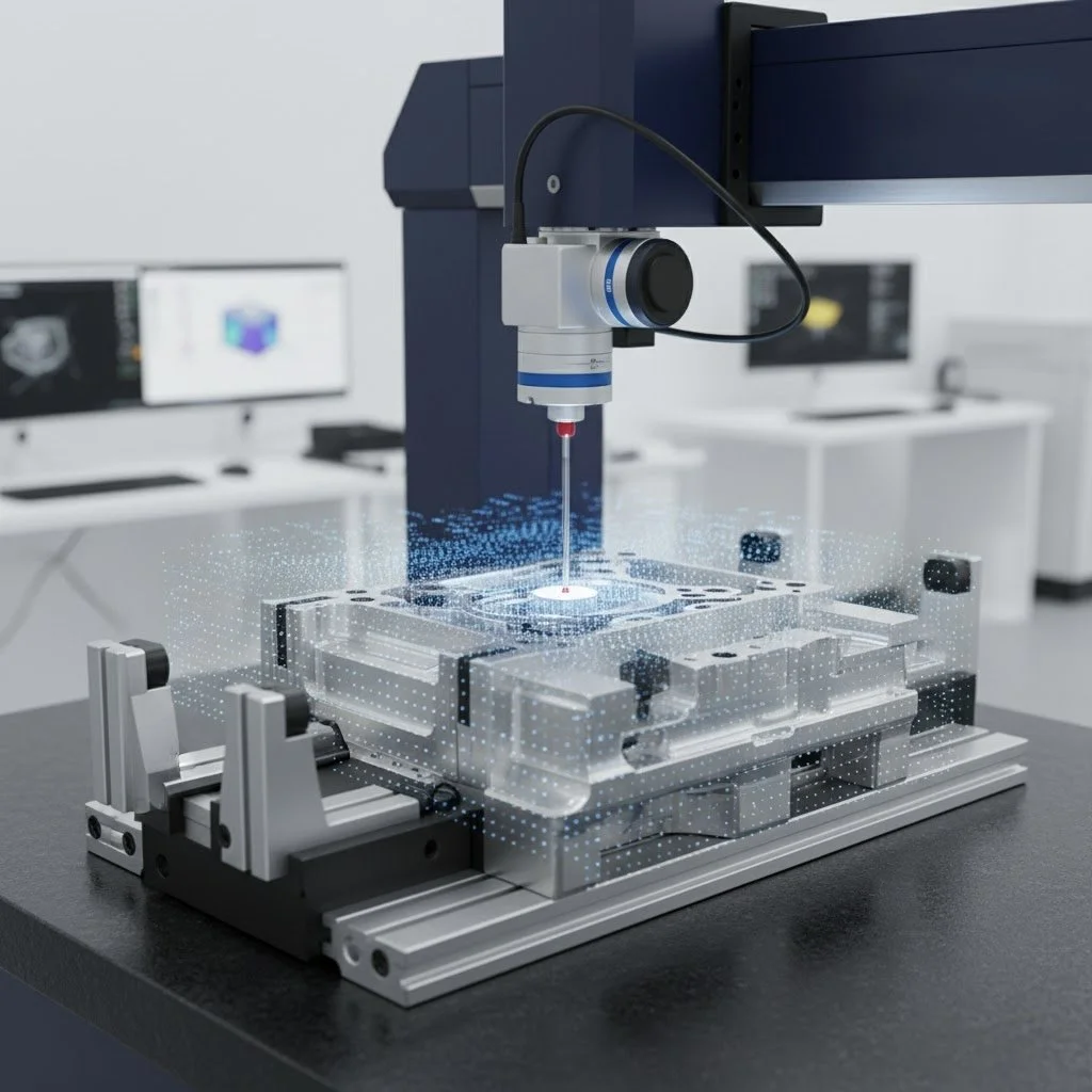
Anchoring Precision: Advanced Metrological Strategies for Primary Datum Plane Establishment on Coordinate Measuring Machines
The integrity of Geometric Dimensioning and Tolerancing (GD&T) specifications hinges entirely upon the stability and accuracy of the Datum Reference Frame (DRF). As the foundation of this framework, the primary datum plane—typically designated Datum A—serves the critical function of establishing the initial orientation and location of a manufactured component in three-dimensional space.

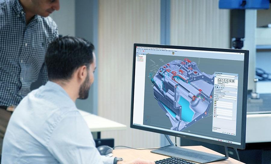
How to choose the right 3D metrology software solution
In manufacturing and quality inspection, selecting the right 3D metrology software solution is essential to ensure accurate results, efficient workflows, and compliance with industry standards. Many companies make the mistake of buying measurement hardware first and then patching together different software tools—which can lead to inconsistent data and wasted effort. In this article, you’ll discover how to evaluate and choose metrology software that supports GD&T, handles large point clouds, integrates across devices, and scales with your operation.

Model to Measurement: Automating Inspection from CAD to Real-Time Quality Control
Mitutoyo Integrated digital inspection ecosystems eliminate manual programming, accelerate reporting, and empower teams to act on live data before parts drift out of specification.

Virtual Advanced GD&T Training on October 14-16. Limited Spots Available!
While the GD&T Fundamentals course teaches a core framework for understanding GD&T, the Advanced GD&T course builds upon this to give students a more comprehensive understanding of GD&T standards and their application. GD&T standards cover every manufacturing application across every industry, and this course fleshes out our Fundamentals course framework to show how GD&T is applied for better design for manufacturability.
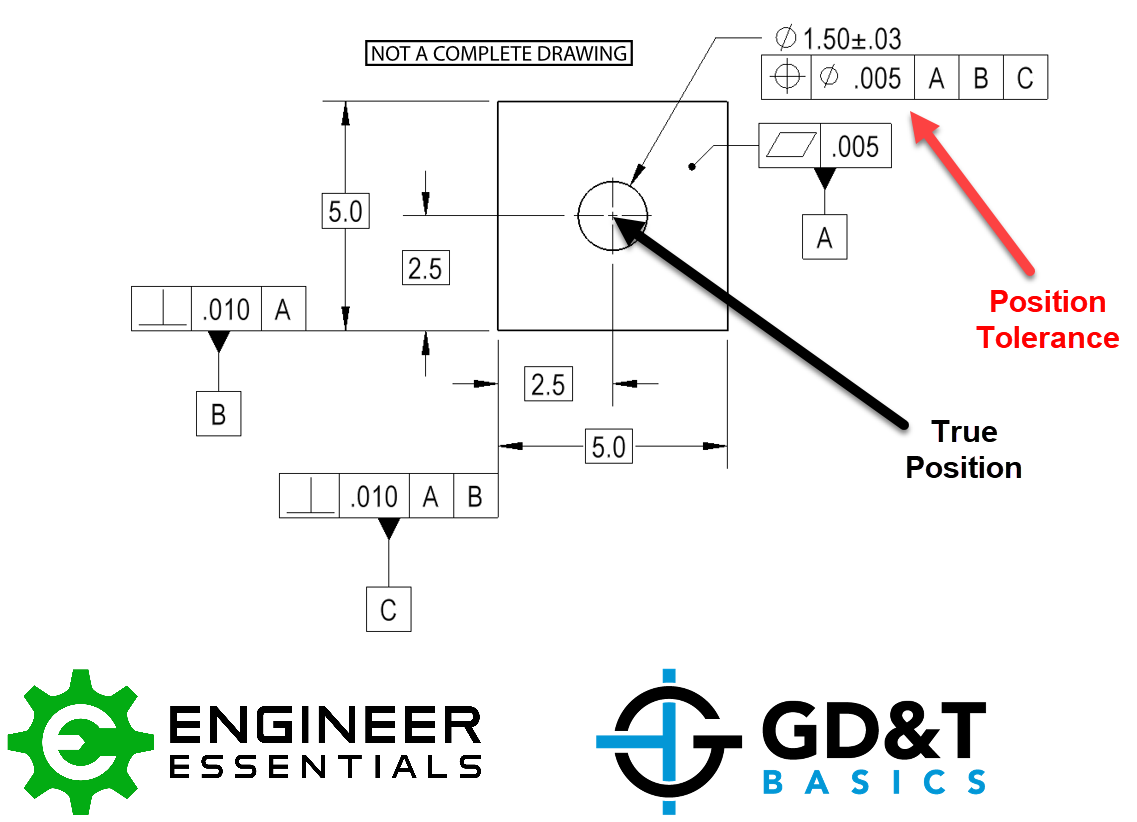
Ensuring Parts Fit, Using Bonus Tolerance to Your Advantage
Designers can use ASME Geometric Dimensioning and Tolerancing (GD&T), an internationally recognized symbolic language, to describe the acceptable limits of part feature variance.
GD&T’s New Rule and What it means for Measurement
Here we will explore the implications of rule "S" and the limits/requirements of today's metrology as it is applied to these GD&T requirements.

Intelligent Model Based GD&T for Inspection
The central concept embodied in model-based definition (MBD) is that the 3D CAD model provides the detailed product information necessary for all aspects of the product definition. Engineers have wanted to harness the power of MDB for years.
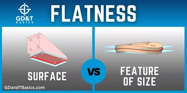
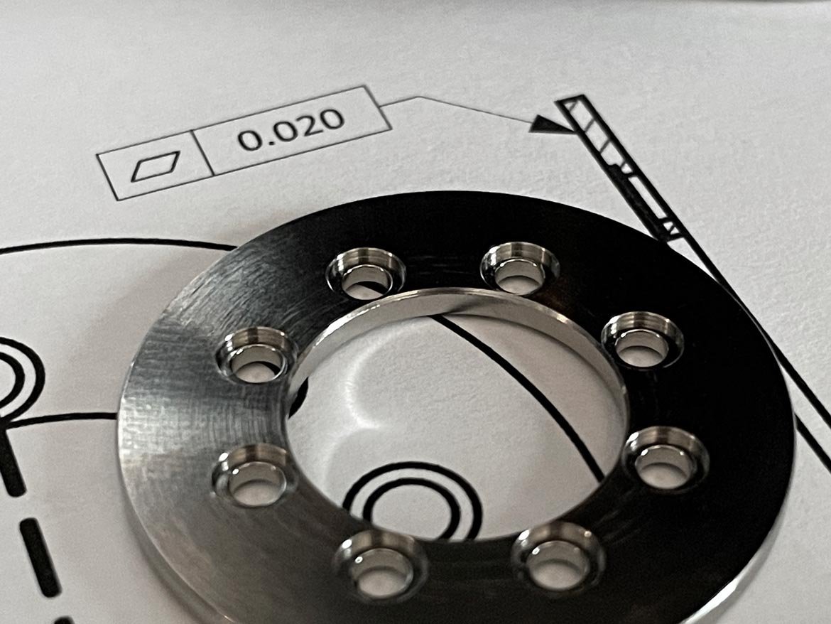
Flatness – Surface vs. Feature of Size
Surface flatness is the type of flatness that most people are familiar with. On a drawing, the flatness callout can point straight to the surface with a leader arrow or be extended out from the surface and away from the feature of size.
Fundamentals Matter: Why GD&T Remains Essential in Modern Manufacturing
In an era where emerging technologies like artificial intelligence, quantum computing, and humanoid robotics dominate the headlines, it’s easy to overlook the foundational principles that make these breakthroughs possible. Yet, behind every cutting-edge application is a bedrock of engineering fundamentals—principles that have guided innovation for decades.
How can GD&T be used to reduce risks in 3D measurement processes?
Geometric Dimensioning and Tolerancing (GD&T) is a system that is used to define and communicate engineering tolerances particularly in the automotive, aerospace, electronics and commercial design industries for the past few decades.
3D Scanning and Model-Based Definition: A New Look at GD&T
The increasing quality and accessibility of 3D scanning tools, particularly computed tomography, are giving quality control experts much more information about the parts they look at, experts say.
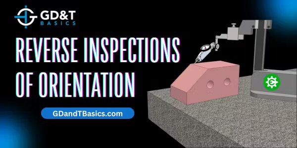
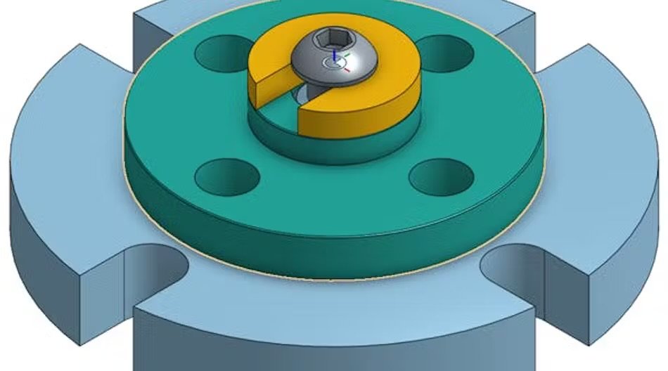
Reverse Inspections of Orientation
I am trying to check the parallelism of the surface of a part in relation to Datum A. Is it acceptable to locate off of the surface of the part and indicate on the Datum A?
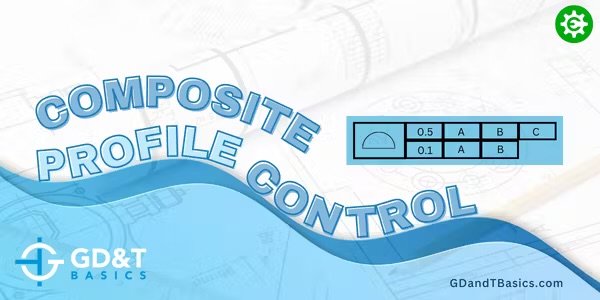
Composite Profile Control
Are the Datum structures in the two examples above valid for this drawing?If they are valid, wouldn’t both examples yield the same results when inspected?

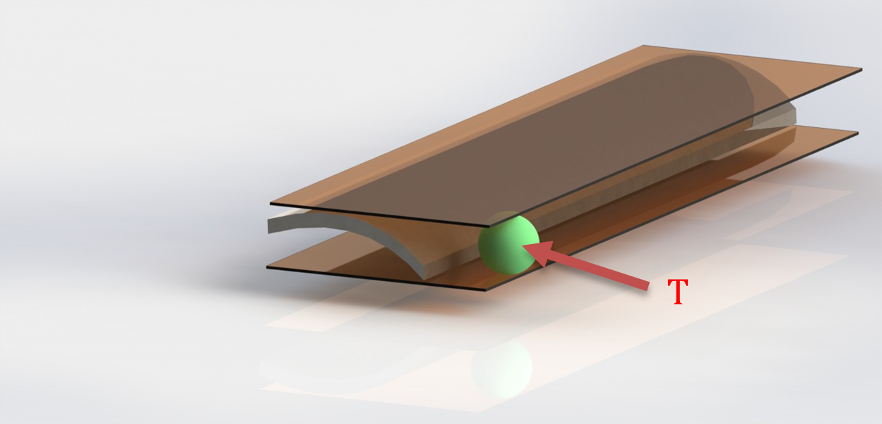
Flatness - GD&T and Calypso Rev 3 Book
Flatness (form tolerance): the tolerance zone is limited by two parallel planes a distance t apart.
Implies: Straightness of the surface or Straightness of the derived median line