
Rotating a Part About a Central Axis: Advantages, Limitations, and Alignment Strategy Tradeoffs
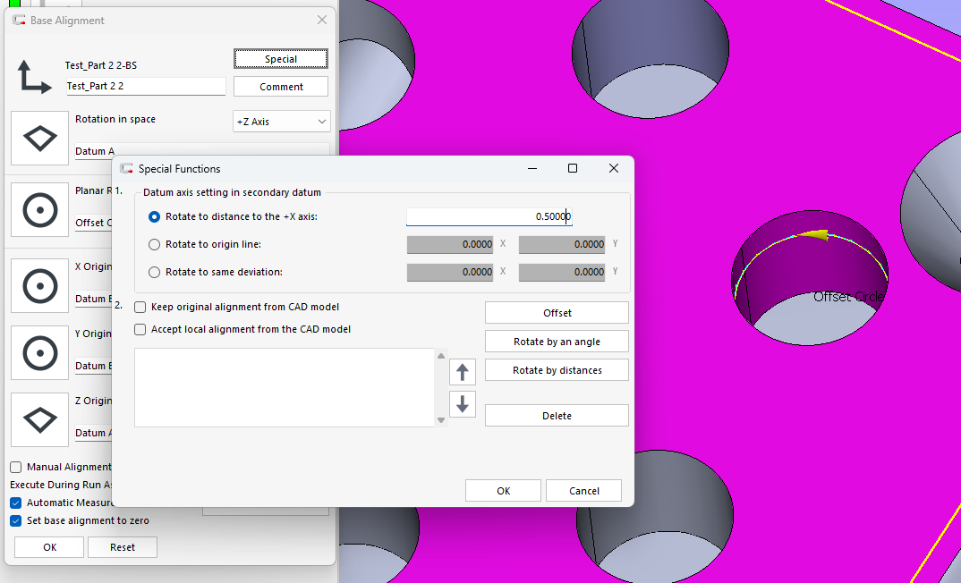
Rotating a measured part about a central axis is a common alignment strategy in coordinate metrology, particularly when inspecting rotationally symmetric parts, bolt circles, turbine components, gears, and multi-feature patterns distributed around a datum axis. While the concept is straightforward, the method used to establish the rotation—whether through fixed offsets, equal-distance offsets, or direct angular rotation—can have significant consequences for measurement stability, error distribution, and traceability to the design intent.
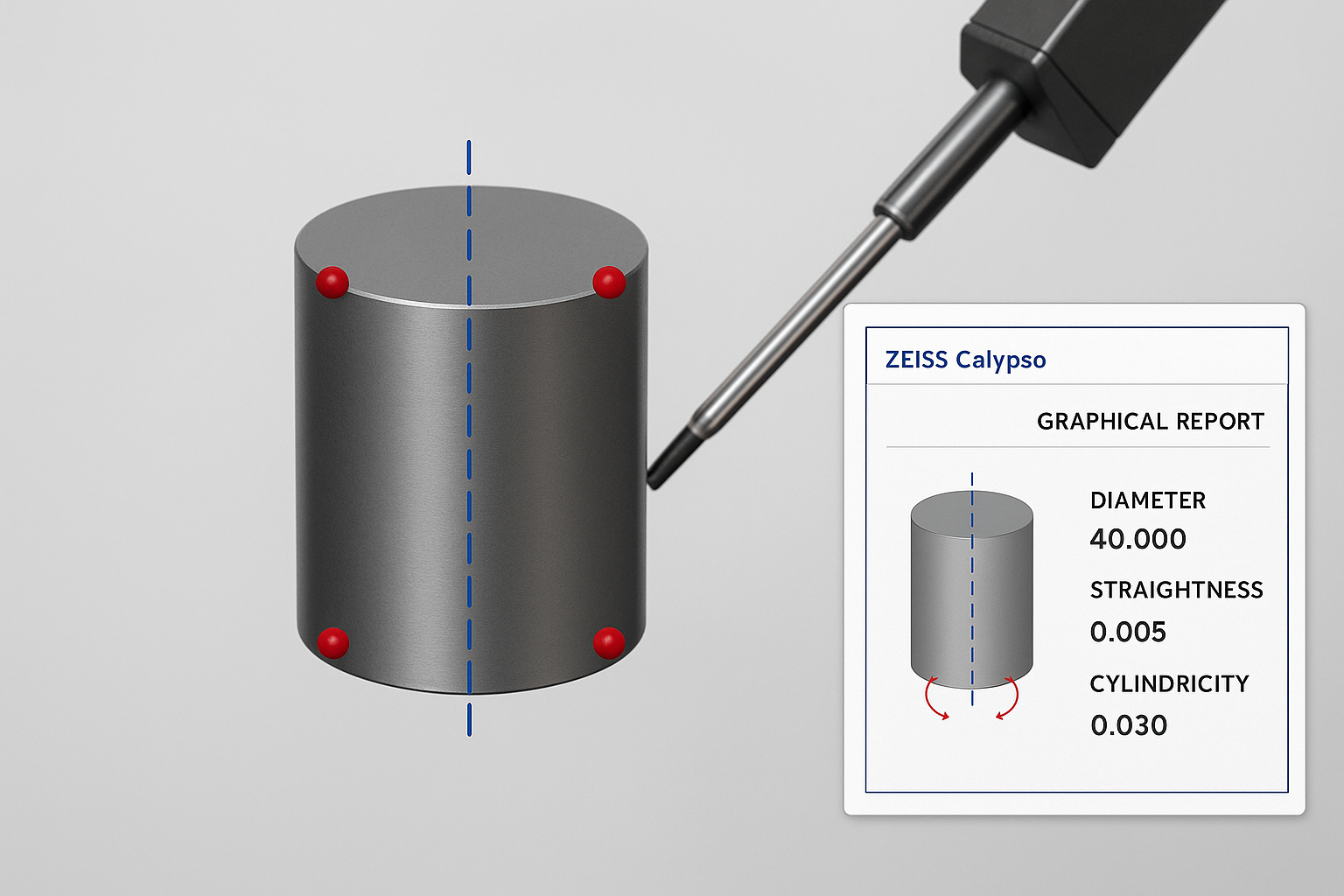
Why a cylinder can be unreliable for spatial alignment
In precision metrology, relying on a full cylinder to define spatial alignment can introduce subtle but significant errors. A fitted cylinder averages all surface deviations, meaning taper, lobing, or localized form errors can tilt or shift the calculated axis. This global best-fit does not always reflect the true functional centerline. In contrast, constructing a 3D line from individual circle sections isolates each cross-section, averages localized imperfections, and produces a more robust datum axis. By understanding how different feature-fitting methods handle form error, CMM programmers can ensure more consistent and functionally accurate measurements — especially in critical alignment operations.