
DMIS - Sensor Setting
An excerpt from the DMIS Handbook. Learn how to write programs in DMIS. This book will help you master the DMIS Language. Sensors Settings.
An excerpt from the DMIS Handbook. Learn how to write programs in DMIS. This book will help you master the DMIS Language.
In these DMIS articles we will start with the basics and move to more complex DMIS statements
Syntax:
SNSET/setting_type (,reference), value

DMIS syntax at the beginning of a program.
SNSET/APPRCH, 5.0000, ON
SNSET/RETRCT, 5.0000, ON
SNSET/SEARCH, 50.0000
SNSET/DEPTH, 3.0000, 3.0000
SNSET/CLRSRF, 30.0000
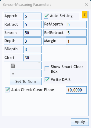
Again, your software input may look different, but it is shown here to demonstrate how a CMM software allows the input that will be written in the DMIS code.
APPRCH
Approach controls the distance from a feature nominal that the CMM will depart the POSVEL (Position Velocity) and move into MESVEL (Measurement Velocity).

SEARCH
Search controls how far the CMM will search for a touch point along the normal vector set in the nominal feature statement.

RETRCT
Retract controls the distance the probe will move away from a probed touch point.
Here we changed the retract to 8mm with a 5 mm approach
Care must be taken in a diameter, slot, etc..., any feature with an opposing wall so that either the approach or the retract will not the wall.

CLRSRF
CLRSRF – provides the clearance plane height for the stylus to travel to the next feature.
CLRSRF
Green - Path with reference
Red - Path without reference
Yellow - CLRSRF
Example:
SNSET/CLRSRF, 30.0000
Sets the clearance surface height to 30mm
Unlock the power of native DMIS (Dimensional Measuring Interface Standard) programming with this hands-on, example-driven digital handbook from CMM Quarterly. Designed to demystify CMM (Coordinate Measuring Machine) scripting, it’s your practical guide to mastering advanced DMIS techniques—all delivered in a downloadable PDF format for convenience and instant access.
What’s Inside
Clear Command Syntax: Grasp key DMIS structures like SNSDEF, CONST/POINT, and the differences between MAJORWORDS and MINORWORDS, with focused explanations for better clarity.
Feature & Tip Definitions: From midpoint calculations to defining custom probe tip shapes (SNSDEF/PROBE,…DISC), practical examples guide you through each step.
Sensor & Mode Programming: Learn crucial DMIS commands—SNSET/APPRCH, RETRCT, CLRSRF, and more—with real-world application examples for reliable routine creation.
Readable Formatting: Consistent layout and color-coding help differentiate keywords from parameters, enhancing comprehension and reducing syntax errors.
Highlights & Audience
Hands-On Learning: Packed full of authentic DMIS code snippets to guide you through common metrology tasks and scripting scenarios.
Ideal for New to Intermediate Users: Perfect for CMM programmers transitioning from GUI-based environments or those aiming to refine DMIS scripts.
Bridges Concept with Practice: Seamlessly takes you from basic syntax to advanced scripting essentials useful in daily use.
Things to Keep in Mind
Not a Substitute for Official Standards: While thorough, it doesn't replace the ANSI/ISO 22093 standard or the NIST DMIS Test Suite for formal compliance or deep technical reference.
Summary
The DMIS Handbook is a strong, example-rich introduction to DMIS scripting—clear, readable, and practical. It’s especially useful for CMM operators, metrologists, and programmers aiming to enhance script accuracy and readability. For best results, pair it with the official ISO/ANSI standards and NIST reference manuals if your work demands strict compliance or integration with advanced systems.
This book is a digital download
Indexing Head with Cylinder or Disc Tip
DMIS statement for creating a cylinder or disc tip.
An excerpt from the DMIS Handbook
DMIS statement for creating a cylinder or disc tip.
Syntax:
S(name)=SNSDEF/PROBE,type,POL,rot1(A),rot2(B),i, j, k, len ,dia, tip(,value)

Example:
S(DISK1)=SNSDEF/PROBE,FIXED,POL,0,0,0,0,1,115,12,DISC,3
The above defines a disc tip (DISK1) that is a fixed probe with a angular rotation of 0/0. The mounting vector is 0, 0, 1 with a length (from pivot center to the tip center) of 115.
The disc diameter is 12mm with a 3mm thickness.

Note: discs and cylinder tips should be used bi-directional, in other words normal to a work plane and not 3 dimensional as a sphere tip would be used.
