How to Use the Virtual Sphere Procedure on Zeiss Calypso
Excerpt from the Calypso Handbook
When calibrating a stylus tip in Calypso software it is recommended that you use Dynamic Tensor calibration at least in the initial calibration. This allows Calypso to gather the “bend data” of each individual stylus. Tensor or Geometric calibration may be used for recalibration purposes.
When using Dynamic Tensor calibration is not uncommon to receive this type of error.
This error requires you to rotate the reference sphere so that Calypso can access an unobstructed path around the reference sphere. To resolve this you may have reloaded the master probe and re-reference the sphere location. Then reloaded the stylus system and went through the entire calibration process.
Next time, try this procedure.
Creating a Set of Virtual Reference Spheres
Within the Stylus System Qualification dialog box click on the Reference Sphere Management icon.
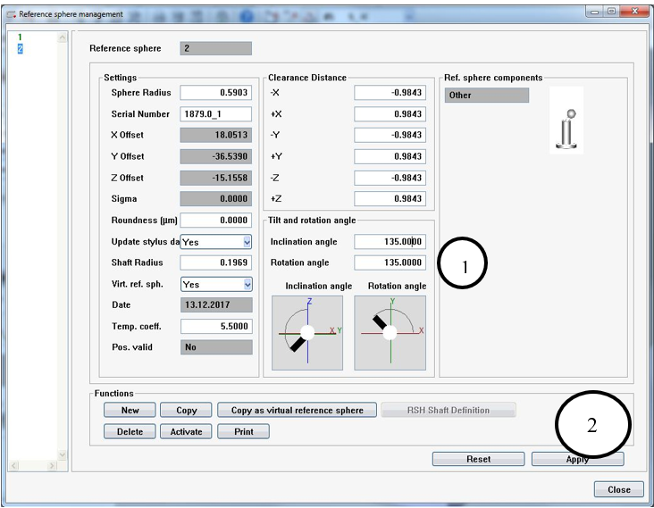
This will open the Reference Sphere Management dialog. It is here that you will create the Virtual Reference Sphere positions. You may create as many positions as you would like. Below in Table 1 are listed the most used positions and these rotations might be a good start.
Above is your default Reference Sphere position screen. We will now add the Virtual Reference Sphere positions. To begin, click on the Copy as Virtual Reference Sphere button. This will bring up this next prompt.
Calypso will automatically select the next number for the reference sphere. Leave the number as is and click ok.
Now another reference sphere is added.
Change the Rotation Angle (1), in this case to 135 degrees, and Click Apply (2).
Let’s add another position. Click back on number 1 in the list and repeat the steps. Click on the Copy as Virtual Reference Sphere button. Name this one #3 and click ok. Highlight #3 in the list and change the rotation angle to 225.00 degrees and click Apply.
Repeat the steps until all of the positions in Table 1 are created.
Remember all these steps where done to circumvent this error during calibration. Once you have completed the above steps it is not necessary to do them again. They will be stored for future use.
Using a Virtual Reference Sphere Position during calibration
The stylus will do a tensor calibration before this error appears.
Once this error has occurred change the Mode to Dyn. Tensor Re-qualification Mode.
Rotate the Master Sphere on the CMM table to the desired position that will allow for a dynamic calibration. It is important to just rotate around the existing position on the table. Do move it to some other location just rotate it around where it is currently located.
Open the Reference Sphere Management dialog
Now select the corresponding Virtual Reference Sphere that matches the new position on the table.
Click Activate. This will now make, in this example, #3 active.
You can now see that the Reference Sphere is Sphere #3
Now click on the Qualify Stylus button.
You are prompted to move the stylus and touch the stylus in the direction of the shaft.
This will now begin the dynamic tensor calibration. This is the scanning of the master ball since the tensor calibration portion was already completed prior to the error
The calibration is complete. Notice the Dynamic Qualification check mark is present and the Mode has changed back to Dynamic Tensor.
NOTE: By using the virtual sphere procedure, you first measure all styli in one position of the reference sphere and only then rotate the sphere to carry out the dynamic stylus qualification. Otherwise, you would have to re-qualify the sphere each time again.


