In the precision-driven world of metrology, where Coordinate Measuring Machines (CMMs) and advanced inspection technologies ensure parts meet exacting standards, Geometric Dimensioning and Tolerancing (GD&T) serves as the universal language for defining and communicating engineering tolerances. At the heart of this system lies ASME Y14.5, the cornerstone standard for GD&T principles. However, to bridge the gap between conceptual rules and rigorous, unambiguous application—particularly in mathematical and computational contexts—ASME Y14.5.1 provides the essential mathematical definitions. This article delves into the specifics of ASME Y14.5.1, exploring its content, mathematical foundations, and critical role in modern metrology. As of late 2025, with ongoing advancements in digital manufacturing and AI-driven inspection, understanding this standard is more vital than ever for metrologists, engineers, and quality professionals.
Overview of ASME Y14.5.1
ASME Y14.5.1, titled “Mathematical Definition of Dimensioning and Tolerancing Principles,” was last revised in 2019 to align with the principles outlined in ASME Y14.5-2018 (reaffirmed in 2024). It builds upon the symbolic and rule-based framework of Y14.5 by offering precise mathematical formulations for GD&T concepts, enabling consistent interpretation and verification of tolerances. This standard is not a standalone guide but a complement to Y14.5, focusing on the geometric mathematics that underpin tolerance zones, datums, and feature controls.
The document is structured logically, beginning with general mathematical principles and progressing to specific definitions for tolerances of form, orientation, location, profile, and runout. Key sections include:
Mathematical Foundations: Definitions of vectors, coordinate systems, and geometric entities like points, lines, planes, and surfaces.
Datum Systems: Formalization of datum reference frames (DRFs) using linear algebra to establish immutable reference points.
Tolerance Zones: Equations describing the boundaries within which actual features must lie, such as cylindrical or spherical zones for position tolerances.
Verification Methods: Algorithms for evaluating compliance, including least-squares fitting and constrained optimization, which are directly applicable to CMM software.
This mathematical rigor eliminates ambiguity, ensuring that GD&T specifications can be translated into programmable inspection routines.
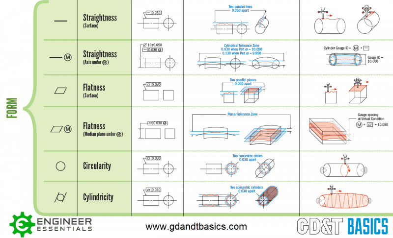
The image above illustrates common GD&T symbols from ASME Y14.5, which Y14.5.1 mathematically defines for precise application.
Key Mathematical Concepts in ASME Y14.5.1
ASME Y14.5.1 transforms GD&T from a visual and interpretive system into a quantifiable one. Below, we break down the core elements with mathematical insights.
Datum Reference Frames (DRFs)
Datums are the foundation of GD&T, providing reference points for measurements. Y14.5.1 defines a DRF as a set of three mutually perpendicular planes established through vector-based operations. For instance, a primary datum plane is derived by minimizing the deviation of points on a feature surface using a least-squares plane fit:

where Xi, Yi, Zi are surface points, and ( a, b, c ) define the plane. Secondary and tertiary datums are then constrained orthogonally. This ensures repeatability in CMM setups, where software aligns parts to these frames for accurate probing. 3
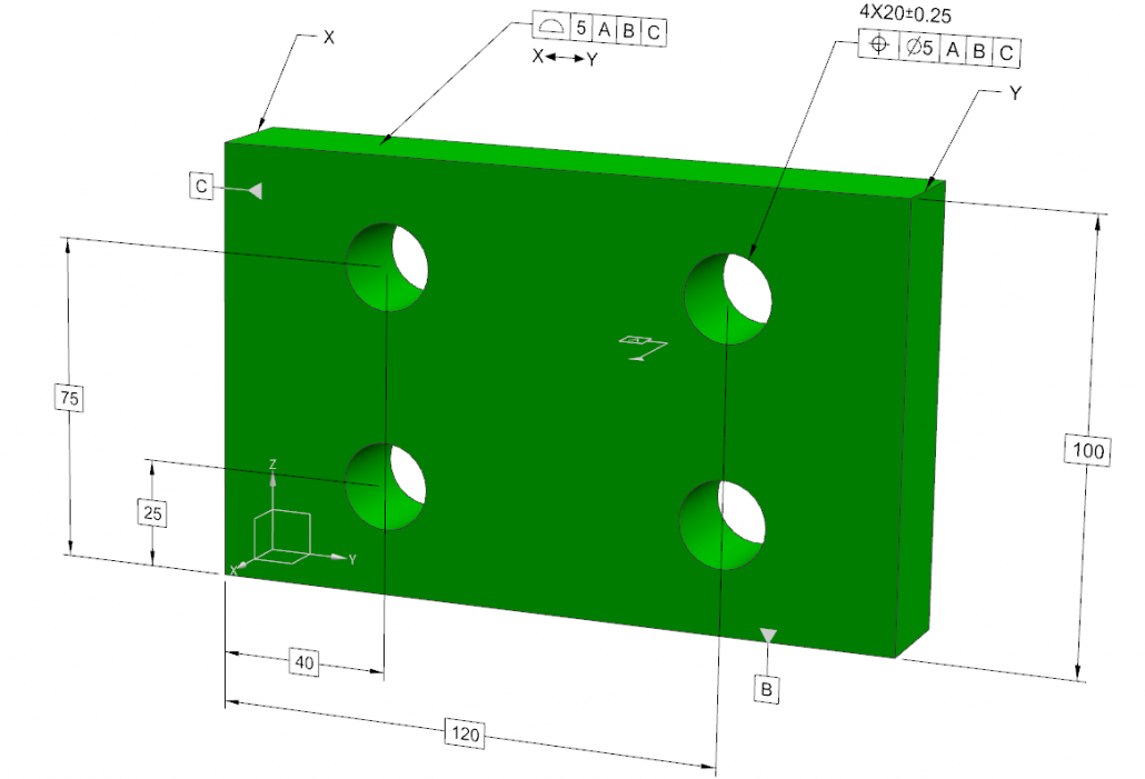
The diagram above shows a typical datum reference frame setup, highlighting how datums constrain degrees of freedom.
Tolerance Zones
Tolerance zones are mathematically bounded regions. For example, a position tolerance at maximum material condition (MMC) is defined as a cylindrical zone of diameter ( t ) centered on the true position, with its axis aligned to the DRF. The actual value is the diameter of the smallest cylinder enclosing all axis points of the feature.
Y14.5.1 uses set theory and inequalities to describe these zones. For a flatness tolerance, the zone is two parallel planes separated by tolerance ( t ), and compliance is checked via:

after aligning to the least-squares plane. 6

This illustration depicts various tolerance zones, demonstrating their mathematical boundaries in GD&T.
Form Tolerances
Form controls like straightness, flatness, circularity, and cylindricity are defined without datums. Y14.5.1 provides equations for each:
Straightness: The feature must lie within two parallel lines (for lines) or a cylinder (for surfaces), minimized via convex hull algorithms.
Flatness: As above, using plane deviation metrics.
Circularity: Deviation from a least-squares circle, calculated as ( R_{\max} - R_{\min} \leq t ).
Cylindricity: Combines circularity and straightness along an axis, often evaluated using helical path deviations. 9
Examples of form tolerances are shown here, with diagrams illustrating acceptable deviations.
Orientation Tolerances
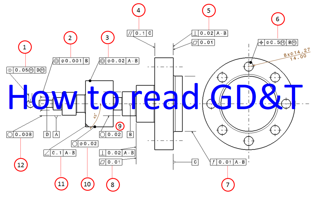
These relate features to datums, such as parallelism, perpendicularity, and angularity. Mathematically, Y14.5.1 defines them as zones parallel or perpendicular to datum planes. For parallelism, the feature plane’s normal vector must satisfy angle constraints relative to the datum normal. 12

Orientation tolerance illustrations, including parallelism and perpendicularity.
Location, Profile, and Runout Tolerances
Location (e.g., Position, Concentricity): Position is a cylindrical or spherical zone; Y14.5.1 uses vector distances from basic dimensions.
Profile (Line or Surface): Defined as a uniform boundary offset from the true profile, evaluated via point-cloud deviation analysis.
Runout (Circular or Total): Measures variation during rotation about a datum axis, mathematically as radial or axial deviations in a polar coordinate system. 15
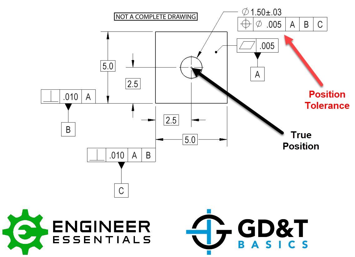
Location tolerance examples, such as true position. 18

Profile tolerance diagrams. 21
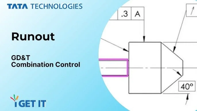
Runout tolerance visuals, showing circular and total runout.
Importance in Metrology and CMM Applications
In metrology, ASME Y14.5.1’s mathematical definitions are indispensable for translating GD&T into verifiable data. Traditional inspection methods rely on subjective interpretation, but Y14.5.1 enables objective, algorithm-based evaluation, directly supporting CMM programming. For instance, the standard’s constrained least-squares algorithm for datum simulation ensures consistent part alignment, reducing measurement uncertainty. 14
This is crucial in industries like aerospace and automotive, where tolerances in microns demand precision.
By providing formulas for tolerance evaluation, Y14.5.1 facilitates automation in CMM software, such as PC-DMIS or Calypso, allowing for batch inspections and statistical process control. It also minimizes disputes between designers and inspectors by offering a common mathematical language, improving quality assurance and reducing costs. 12
In digital twins and Industry 4.0, these definitions integrate seamlessly with CAD/CAM systems for virtual metrology.
Recent Updates and Alignment with Y14.5-2018
The 2019 revision of Y14.5.1 supports updates in Y14.5-2018, including model-based definitions (MBD) and removal of concentricity/symmetry symbols in favor of position/profile. New algorithms, like constrained least-squares for unstable features, address digital inspection challenges. 14
As of 2025, no major revisions have been announced, but ongoing work in ASME committees may incorporate AI-enhanced metrology in future editions. 17
Conclusion
ASME Y14.5.1 elevates GD&T from art to science, providing the mathematical backbone for precise metrology. For CMM professionals, mastering this standard means achieving repeatable, accurate inspections that drive manufacturing excellence. As technologies evolve, its principles remain timeless, ensuring parts fit, function, and perform as intended.
References
ASME Y14 Standards. https://www.asme.org/codes-standards/y14-standards 0
Mathematical Definition of Dimensioning and Tolerancing Principles. https://www.asme.org/codes-standards/find-codes-standards/y14-5-1-mathematical-definition-dimensioning-tolerancing-principles 1
The ASME Y14.5 GD&T Standard. https://www.gdandtbasics.com/asme-y14-5-gdt-standard/ (Published July 24, 2020) 2
The Ultimate Guide to ASME Y14.5 [2025 Edition]. https://www.sigmetrix.com/blog/ultimate-guide-to-asme-y14.5 (Published October 15, 2025) 3
ASME Y14.5 & ASME Y14.100 Standards: GD&T and Drawings. https://blog.ansi.org/ansi/what-are-the-asme-y14-5-and-asme-y14-100-standards/ (Published March 31, 2023) 5
ASME Y14.5-2018 Changes & Key Differences from 2009. https://geotol.com/2018-standards/ 7
ASME Y14.5 - Wikipedia. https://en.wikipedia.org/wiki/ASME_Y14.5 8
ASME Y14.5 - Wikipedia. https://en.wikipedia.org/wiki/ASME_Y14.5 (Published February 12, 2025) 11
ASME Standards for GD&T: The Backbone of Metrology Labs. https://www.nelpretech.com/blog/asme-y14-5-standard-the-backbone-of-metrology-labs (Published July 9, 2024) 12
Y14.5 - Dimensioning and Tolerancing. https://www.asme.org/codes-standards/find-codes-standards/y14-5-dimensioning-tolerancing 13
ASME Y14.5-2018 Changes & Key Differences from 2009. https://geotol.com/core-programs/2018-standards/ (Published October 3, 2025) 14
Metrologists Compare ASME Y14.5-2018 vs. ASME Y14.5-2009. https://measuremetrology.com/asme-has-just-released-y14-5-2018-whats-new/ (Published October 1, 2025) 15
The Ultimate Guide to ASME Y14.5 [2025 Edition]. https://www.sigmetrix.com/blog/ultimate-guide-to-asme-y14.5 (Published October 15, 2025) 17
ASME Y14.5 & ASME Y14.100 Standards: GD&T and Drawings - The ANSI Blog. https://blog.ansi.org/ansi/what-are-the-asme-y14-5-and-asme-y14-100-standards/ (Published March 31, 2023) 18
ASME Y14 | Y14 Standards - ASME. https://www.asme.org/codes-standards/y14-standards 19