By Mark Boucher - CMM Quarterly
Section 1: Introduction to Precision Metrology Fixturing
1.1 The Role of Fixtures in Minimizing Measurement Uncertainty
Coordinate Measuring Machines (CMMs) represent the foundational technology for precision quality control in modern manufacturing, largely replacing traditional, time-intensive methods reliant on single-purpose gauges and inspection fixtures. While CMMs offer unparalleled capability to inspect complex geometries, including airfoils, gears, and camshafts, the ultimate accuracy realized in production relies critically on the stability of the part setup. The CMM’s inherent precision is inherently compromised if the workpiece moves or is positioned inconsistently during the measurement routine.
The primary mandate of CMM fixture design is the assurance of precision and repeatability. Fixtures are engineered to maintain stable part positioning throughout the entire measurement cycle, a requirement that minimizes positioning errors, suppresses movement and vibration, and ultimately ensures the consistency and reliability of the measurement results. Achieving stable part holding is not merely a convenience but a critical factor in maintaining product quality and reducing rejection rates, especially in high-volume, precision-dependent industries such as aerospace and automotive production.
Beyond metrological accuracy, fixture design significantly impacts operational efficiency. High-quality fixturing systems reduce setup time, eliminate the need for repeated manual adjustments, and streamline the overall measurement workflow. This increased productivity and throughput, coupled with a decrease in measurement errors, translates directly into cost savings by reducing material waste, lowering rework likelihood, and minimizing production delays. Furthermore, well-designed fixtures improve the economy of production by simplifying the process of mounting workpieces, thereby reducing the dependency on highly skilled labor for repetitive setup tasks and allowing for quicker transitions between parts. This strategic investment in robust fixturing is therefore justified not only by quality imperatives but also by tangible economic benefits derived from operational consistency.
1.2 Classification of CMM Fixtures: Dedicated, Modular, and Universal Systems
CMM fixtures are generally categorized based on their intended use, flexibility, and investment requirements. The selection of a fixture architecture is typically driven by production volume, part complexity, and the anticipated longevity of the part design.
Dedicated Fixtures are custom-engineered for a single specific part or a closely related family of designs. This tailored approach offers the maximum degree of precision and repeatability because all potential variables are engineered out of the system. Dedicated fixtures are typically reserved for high-volume production runs where the initial investment cost, which can range significantly per fixture and require weeks of validation, is offset by the sustained demand and the need for uncompromising accuracy.
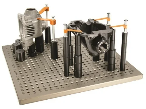
Modular Fixtures represent a highly flexible alternative. These systems are constructed from standardized, reconfigurable components, including interchangeable grid plates, adjustable clamps, and quick-change locators. Modular systems are ideal for manufacturing environments characterized by varied production lines, high part mix, and low volume. Their primary advantage is agility, allowing operators to assemble and disassemble fixtures quickly for various parts and reuse the components repeatedly. This versatility allows job shops to quickly respond to customer needs and amortize the cost of fixturing components across multiple, distinct jobs. Critically, specialized dedicated fixtures can sometimes be constructed using modular components. If the part design becomes obsolete, the components can be easily broken down and reintegrated into the modular inventory, avoiding the traditional waste associated with entirely dedicated tooling.
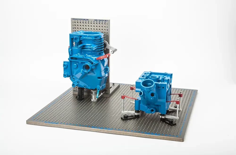
Image: Rayco Fixtures
Universal Fixtures offer the greatest versatility, accommodating a wide range of geometries with minimal modification. However, this breadth of application often requires compromises in precision when compared to dedicated or carefully configured modular setups.
Section 2: Kinematic Principles and the Degrees of Freedom (DOF) Constraint
2.1 Defining Degrees of Freedom (DOF) and the Datum Reference Frame (DRF)
Accurate metrology hinges on the ability to precisely and repeatedly locate a part in three-dimensional space. A rigid body, prior to being fixtured, possesses six independent degrees of freedom (DOF). These consist of three translational movements along the primary axes (Tx, Ty, Tz) and three rotational movements (Pitch Rx, Roll Ry, and Yaw Rz) about those axes.
The role of the fixture is to eliminate these six DOF completely. This is achieved through the implementation of the Datum Reference Frame (DRF), which is the theoretical coordinate system specified on the engineering drawing, typically adhering to Geometric Dimensioning and Tolerancing (GD&T) standards. The DRF defines the location of the part by constraining the six DOF, fixing its position and orientation in space. The physical fixture must realize the DRF defined by the primary, secondary, and tertiary datums on the blueprint. The CMM software alignment routine (which controls the rotational constraints via I, J, K vectors and translational constraints via X, Y, Z locations) must directly correspond to the physical constraint provided by the fixture.
2.2 The 3-2-1 Locating Principle: Full Kinematic Constraint
The industry standard for achieving full kinematic constraint is the 3-2-1 locating principle, also known as the six-point positioning principle.This methodology stipulates that six passive locators, applied in a specific sequential order, are necessary and sufficient to eliminate all six degrees of freedom of a workpiece.
The principle works by pressing the workpiece against three adjacent locating surfaces defined by the blueprint's datum scheme. Once constrained by the six locators, the workpiece occupies the single, mathematically determined position in the fixture, ensuring mechanical repeatability.
It is essential to distinguish between the locators and the clamping forces. The locators are passive fixture elements that define the position. Clamping is the application of external, usually directional, force required to maintain firm contact between the part and these locators. Clamping force is responsible for counteracting the effects of gravity, measurement probing forces, or vibration, but the clamps themselves do not count as locators and do not restrict DOF. Understanding this distinction is fundamental to avoiding over-positioning, which is a primary source of measurement error and part deformation.
2.3 Sequentiale Constraint Mapping: Primary, Secondary, Tertiary Datums
The 3-2-1 principle translates the abstract DRF into a sequential, physical system of constraint:
A. Primary Datum (3 Locators)
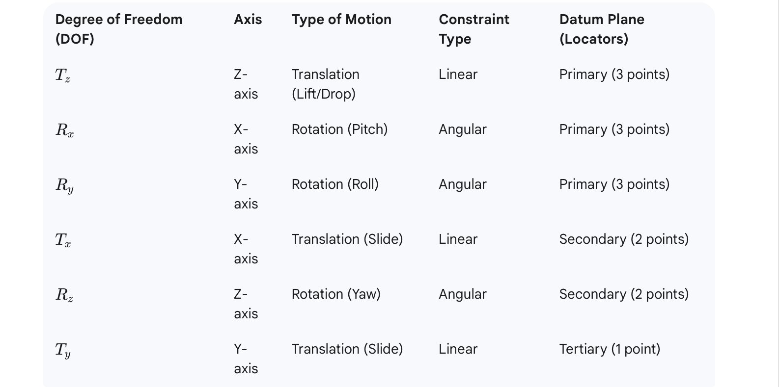
The primary datum is typically realized by three support points placed on the largest, most stable surface of the part.10 These three points establish the primary datum plane. This plane restricts five degrees of movement: linear movement along the axis normal to the plane ($T_z$) and the two rotational movements about the plane’s axes (Pitch $R_x$ and Roll $R_y$). To ensure maximum stability, the three support points must be spaced as far apart as possible.
B. Secondary Datum (2 Locators)
Following the primary datum, the secondary datum plane is established by two additional locators. This plane must be perpendicular to the primary datum plane.10 The secondary datum is often used in the CMM alignment process to rotate the part to align with a specific CMM axis. The two locators restrict two further degrees of movement: linear movement along the axis normal to the secondary plane ($T_x$) and the remaining rotational movement (Yaw $R_z$).
C. Tertiary Datum (1 Locator)
The final single locator establishes the tertiary datum plane, which is perpendicular to both the primary and secondary planes.10 This single point locks the remaining degree of freedom, restricting linear movement along the tertiary plane's axis ($T_y$).12 Once this final contact is made, the part is fully constrained in its required orientation and position, and all six DOF are eliminated. Table 2.1 provides a complete breakdown of how the six degrees of freedom are sequentially constrained by the locators.
Table 2.1: Six Degrees of Freedom and Constraint
2.4 Over-Positioning and Under-Positioning: Error Avoidance
Deviation from the fundamental 3-2-1 kinematic principle introduces significant risk to measurement integrity.
Under-Positioning occurs when necessary degrees of freedom are not adequately restricted, resulting in part movement or non-conforming placement. This scenario is universally prohibited as it renders the measurement results unreliable.
Over-Positioning involves restricting one or more degrees of freedom redundantly, meaning more than six rigid locators are used. This practice is generally forbidden in precision fixturing because it directly causes part deformation. If a part is forced against seven fixed points, the seventh point introduces internal stress and elastic strain by compelling the part geometry to conform to the fixture, rather than allowing the fixture to conform to the part's inherent, though tolerated, geometry. This internal strain alters the part's true condition, thereby directly violating the metrology goal of measuring the manufactured state of the workpiece. Thus, strict adherence to the kinematic 3-2-1 locator scheme serves as the foundational design defense against mechanical deformation.
Section 3: Translating GD&T Datums into Physical Fixture Locators
3.1 Designing Physical Locator Geometry and Placement
The transformation of theoretical datum planes specified in a GD&T model into physical fixture elements requires meticulous design implementation. The physical placement of locators must prioritize stability and rigidity. As established, the primary datum should leverage the largest available surface area of the workpiece, and the three supporting locators should be placed as far apart as possible to maximize the locator base and prevent rotational deflection.
For non-rigid or thin-walled workpieces that are prone to sag or deflection, additional supports may be required beyond the required six kinematic locators. In such cases, these supplementary points are intended to manage the mass and gravity effects but must be adjustable. By making them adjustable, they can be configured to touch the part without exerting pressure that restricts any of the six degrees of freedom, thus preventing them from acting as redundant, over-constraining locators.
Fixtures, especially those used for critical inspection processes, must adhere to defined tolerance and documentation standards. Specific requirements often dictate that the fixture's internal coordinate system (its "gage certification datum scheme") is defined by tooling balls or the base surface itself, which establish the physical reference planes for the primary, secondary, and tertiary datums.
3.2 Ensuring Accessibility and Minimizing Interference
A CMM fixture must not only secure the part accurately but also grant the CMM probe unimpeded access to all features specified in the inspection routine. The fixture design must provide an unobstructed probe path to inspect every critical detail on the part.
Clamping elements and locators represent a primary source of interference. They must be carefully positioned so they do not obstruct or hinder the CMM stylus access to critical measurement features, particularly the datum features used for alignment. Preferred clamps, such as low-level bayonet or toggle clamps, should be selected and positioned well away from the part edges to maximize CMM access.
For complex inspection tasks, developing a formal fixturing strategy document is a crucial prerequisite for successful and repeatable measurement. This strategy specifies the exact clamping sites, the required clamping force, and the precise sequence of clamping and probing. This rigorous documentation maximizes probe accessibility and guarantees that the measurement program is reproducible regardless of the operator or measurement cycle. Furthermore, Computer-Aided Design (CAD) data analysis must be employed prior to execution to simulate the probing routine and detect any potential collisions between the stylus and the part or the fixture.
Section 4: Advanced Principles for Non-Deforming Part Clamping
4.1 The Physics of Clamping Stress and Deformation
After establishing the part's position using the 3-2-1 kinematic principle, the clamping system's sole purpose is to apply sufficient external force to secure the part against the locators. The paramount challenge is to apply this force without inducing elastic or plastic strains that distort the part’s nominal geometry.
For parts with thin walls, which are highly susceptible to warping, this constraint is particularly acute. A key strategy in mitigating localized deformation is the strategic distribution of force. Instead of relying on a single large clamp, the use of multiple, smaller clamps positioned strategically ensures that the total required holding force is spread more evenly across the part surface, minimizing high-stress pressure points.
The material designer can also contribute to metrological stability by prioritizing deformation-resistant part geometries in the original design, such as specifying thicker walls (e.g., thicker than 1.5 mm) or integrating reinforcing ribs and supports.22 When part features are inherently more stable, the constraints on clamping force become less stringent, simplifying the fixture design challenge.
4.2 Specialized Non-Marring Clamping Techniques
For highly sensitive or complex parts, standard mechanical clamping may be inappropriate, necessitating the use of specialized techniques that manage force dynamically or distribute it universally.
A. Vacuum Fixturing (Negative Pressure Constraint)
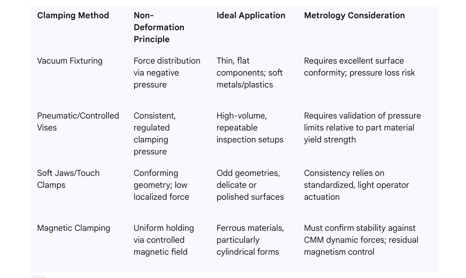
Vacuum clamping secures workpieces by creating negative pressure across the contact surface, effectively spreading the holding force uniformly. This technique is celebrated for minimizing localized pressure points that cause deformation, making it highly effective for thin, flat components, soft metals, and plastics.
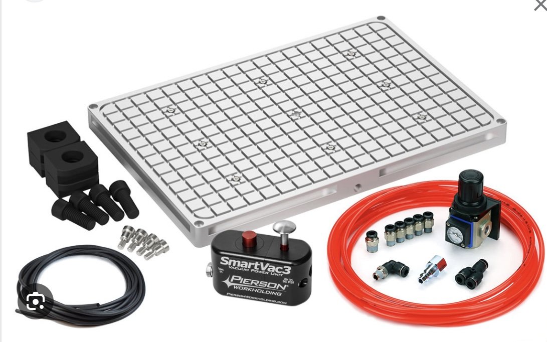
Image: Pierson Workholding
However, vacuum fixturing relies heavily on seal integrity. Soft materials are particularly suited because they undergo a slight, controlled deformation during suction, which helps form a tighter, more effective seal with the clamp surface. This phenomenon represents a critical paradox: a method designed to prevent measurement deformation relies on a small degree of controlled elastic deformation for efficient workholding. The fixture designer must confirm that this required seating deformation does not exceed the allowed part tolerances, ensuring that workholding efficiency does not compromise GD&T compliance. Conversely, hard materials with uneven surfaces often fail to conform adequately, leading to air leakage and insufficient holding force. Furthermore, materials that are semi-porous or porous place high demands on the volume and performance of the vacuum pump required to maintain adequate clamping force.
B. Controlled-Force Systems (Pneumatic and Magnetic)
Advanced clamping systems leverage controlled actuation mechanisms to ensure consistency and repeatability, removing the variability inherent in manual clamping. Pneumatic vises, for instance, utilize regulated air pressure to deliver a consistent, repeatable clamping force regardless of the individual operator who loads the part. These systems are capable of providing precise, gentle clamping forces suitable for delicate parts, or high forces (up to 150 lbs, depending on regulation) when necessary.8 Magnetic clamping systems utilize technology such as hybrid chucks or square pole technology. These systems can align and clamp ferrous workpieces using a brief electrical pulse to activate a permanent magnet, securing the part without continuous energy input. This method facilitates low-deformation clamping, particularly for cylindrical parts, by ensuring uniform holding across the surface.
C. Soft-Touch and Conformable Clamps
For parts with complex, non-standard, or delicate surfaces, the use of soft jaws or dedicated soft-touch clamps is recommended. These clamps are typically manufactured from materials that conform to the part's contours without creating high-stress concentration points. Soft-touch clamps made of plastic are available in standard CMM fixturing kits, providing a low-force option to fix parts in position after the locators have defined the orientation.
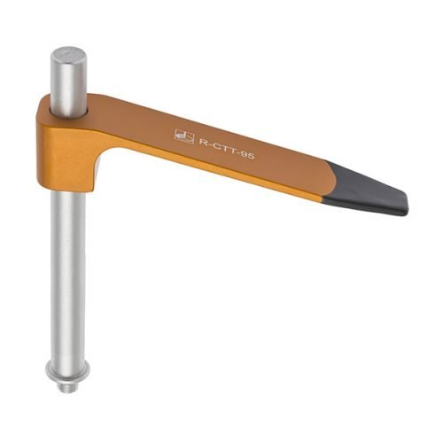
Table 4.3: Comparison of Non-Deforming Clamping Techniques
Section 5: Material Selection and Thermal Management in Precision Fixturing
5.1 The Criticality of Coefficient of Thermal Expansion (CTE)
Thermal management is an often-underestimated source of measurement uncertainty in precision metrology. Temperature fluctuations inherent in the CMM environment can cause thermal expansion or contraction, resulting in changes to the part's geometry and position. For maximum accuracy, the thermal stability of the entire part-fixture assembly must be guaranteed.
A principal risk arises from a mismatch in the Coefficient of Thermal Expansion (CTE) between the measured workpiece and the materials used in the fixture or the CMM base platform (typically granite). If the measured part and the fixture material possess significantly divergent CTEs, even minor temperature variations will cause them to expand or contract at different rates.
If the part is rigidly secured—for example, bonded directly to the granite countertop—the CTE mismatch prevents the part from expanding freely. This differential expansion imposes immense internal stresses and strain on the workpiece, physically altering its measured geometry. This scenario of thermally induced deformation can be significant enough to affect the part's true condition or even risk warping the CMM table.
5.2 Strategies for Mitigating Thermal Mismatch Deformation
To maintain measurement accuracy and prevent thermal strain, several mitigation strategies are employed:
Strategy 1: CTE Matching. The ideal solution involves selecting fixture materials, particularly for critical elements like base plates, that have a CTE comparable to that of the measured workpiece or the CMM platform. Common base plate materials, such as cast aluminum with a hard-coat anodize finish, are selected for their combination of wear resistance and thermal properties.
Strategy 2: Environmental Control. If exact material matching is impractical, the measurement environment must be rigorously controlled. The fixturing method should only be employed under conditions where there is no noticeable change in the indoor temperature, ensuring that both the part and the fixture remain thermally stable throughout the inspection cycle.
Strategy 3: Elastic Decoupling. When rigid fixation methods, such as adhesive bonding, are necessary for specific part geometries, the use of elastic restraint materials (e.g., silicone rubber) is essential. Applying an elastic layer between the part and the rigid fixture or granite table allows the part to expand and contract freely, effectively decoupling the thermal strains and preventing thermally induced deformation. This requirement for elastic materials introduces a crucial trade-off: metrology demands rigidity for kinematic placement, yet thermal stability often requires a degree of elasticity. Expert fixture design involves balancing this need for rigidity (kinematic stability during probing) against the need for elasticity (thermal decoupling) based on the specific tolerance requirements and the volatility of the thermal environment.
5.3 Durability and Wear Resistance
Long-term repeatability in fixture systems requires materials that can withstand the physical demands of repeated loading, unloading, and cleaning cycles. Hard-coat anodized cast aluminum is often used for base plates due to its resistance to wear and scratching, thereby maintaining the geometric integrity of the fixture foundation over time. The selection of robust materials for locators and clamps is equally important to ensure that component wear does not compromise the precise location defined by the 3-2-1 principle.
Section 6: Fixture System Selection and Implementation Strategy
6.1 Comparative Analysis: Modular vs. Dedicated Architectures
The decision between dedicated and modular fixturing systems is a strategic investment choice driven by manufacturing volume and long-term part stability. Dedicated fixtures, which can cost significantly and require extensive design and validation efforts, are primarily justified for high-volume manufacturing programs with predictable longevity.
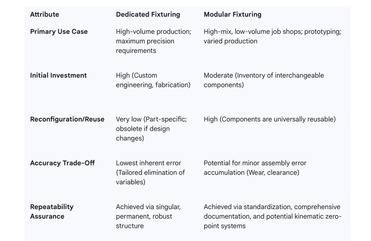
Modular systems, conversely, cater to the agility required by high-mix, low-volume job shops. While dedicated systems minimize all variables for maximum accuracy, modular systems rely on standardized components that can introduce minor potential error sources, such as slight wear on mating surfaces or small bolt clearances.6However, modular solutions offer substantial flexibility, often transitioning seamlessly into automated robotic cells with minimal reconfiguration, providing a future-proof solution that is difficult for static dedicated tooling to match. Table 6.1 summarizes the key differentiators for fixture system selection.
Table 6.1: Comparative Analysis of Fixture System Architectures
6.2 The Role of Kinematic Mounts in Repeatability
Kinematic mounting systems are a specialized solution used to enhance the repeatability of fixture placement, particularly valuable in automated CMM environments. These systems function as precise, quick-change zero-point interfaces, allowing an entire fixture assembly—whether dedicated or modular—to be removed and replaced onto the CMM base plate with exceptional accuracy.
By ensuring that the interface between the fixture assembly and the CMM platform is itself highly repeatable, kinematic mounts effectively minimize the setup variability that can plague modular systems. They provide a robust mechanical means of guaranteeing that the recorded fixture configuration is reproduced exactly, thereby closing the accuracy gap between the flexibility of modular components and the demanding precision of dedicated setups.
6.3 Documenting Fixture Setup for Traceability and Repeatability
Repeatability in CMM metrology is not solely a function of mechanical design; it also requires stringent process control. Consistent setup procedures are mandatory to minimize variability across inspection cycles.
Modern modular fixturing systems support this requirement through standardization. Base plates are often labeled alpha-numerically, providing a simple, quick method for operators to precisely record and reproduce the exact location and configuration of all fixturing elements. This systematic documentation facilitates the fast and accurate repetition of complex setups, directly supporting the core mandate of repeatability. As part of the fixturing strategy, a comprehensive document detailing clamping locations, force, and sequence guarantees that the measurement program remains reproducible and traceable.
6.4 Operator Training and Ergonomics
The human factor in fixturing directly influences measurement variability. Fixtures must be designed with ergonomics in mind to minimize operator strain and fatigue and facilitate easy loading and unloading.
A fixture that is ergonomically challenging increases the likelihood of human-induced errors, such as inconsistent application of clamping force or improper part seating against the locators. If a fixture is difficult to use, operators are more likely to deviate from the rigorous documented strategy, compromising the intended reproducibility of the measurement program.21 Therefore, integrating strong ergonomic principles into fixture design is a critical mechanism for mitigating human variability and enhancing the overall repeatability of the CMM process.
Section 7: Conclusion
The design of Coordinate Measuring Machine fixtures is a multidisciplinary engineering challenge that synthesizes principles from mechanical kinematics, material science, and process control. An expert-level fixture must successfully achieve three intertwined objectives:
Kinematic Precision (Datum Adherence): The fixture must rigorously adhere to the 3-2-1 locating principle, constraining the part's six degrees of freedom using exactly six passive locators mapped directly from the Datum Reference Frame (DRF) defined on the blueprint. Failure to adhere to this principle—specifically through over-positioning—is a direct cause of mechanical deformation and measurement error.
Non-Deforming Constraint (Clamping): The clamping mechanism must apply force sufficient only to secure the part against the locators, without inducing geometric strain. This requires advanced techniques such as vacuum clamping for thin parts, or controlled pneumatic/magnetic systems, coupled with soft-touch materials, to ensure even force distribution.
Thermal Stability (Material Management): The fixture and part assembly must be resistant to environmental fluctuations. When possible, the Coefficient of Thermal Expansion (CTE) of the fixture material should match the workpiece. Where rigid fixation is required, the strategic deployment of elastic restraint materials is necessary to decouple thermal strain and prevent temperature-induced geometric deformation.
The future of high-precision fixturing is moving toward greater automation and adaptability. The widespread adoption of modular systems, supported by kinematic quick-change mounts and integrated pneumatic or magnetic clamping, allows manufacturers to achieve the repeatability traditionally reserved for dedicated fixtures while retaining the necessary agility for dynamic production environments. Investing in comprehensive design strategies, robust documentation, and continuous operator training remains essential to translating the potential accuracy of the CMM and fixture system into verifiable, repeatable quality control outcomes.