Introduction
Coordinate Measuring Machines (CMMs) are central to dimensional quality assurance. However, like all physical systems, they are subject to geometric inaccuracies introduced through mechanical wear, assembly tolerances, and environmental conditions. To maintain traceable, high-precision measurements, these machines undergo volumetric compensation—a process that quantifies and mathematically corrects spatial errors across the entire measuring volume.
This guide outlines the theory, measurement setup, error modeling, real-world application, and visual tools to understand and perform volumetric compensation effectively.
1. Understanding Volumetric Errors in CMMs
Volumetric errors in a CMM stem from deviations in linear motion, angular alignment, and squareness between machine axes. In total, a standard 3-axis Cartesian CMM can accumulate 21 independent geometric errors:
Types of Errors:
Linear Positioning Errors (Exx, Eyy, Ezz)
Straightness Errors (Exy, Exz, Eyx, Eyz, Ezx, Ezy)
Angular Errors (Pitch, Roll, Yaw around each axis)
Squareness/Orthogonality Errors (Eyzx, Ezxy, Exyz)
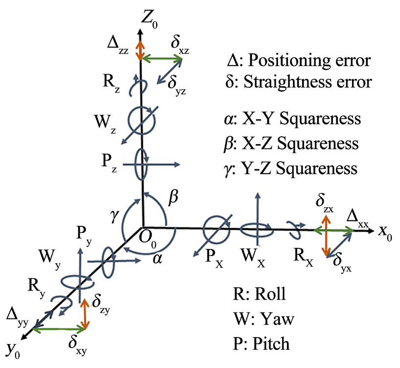
Image: ResearchGate
2. Setting Up the Laser Interferometer for Calibration
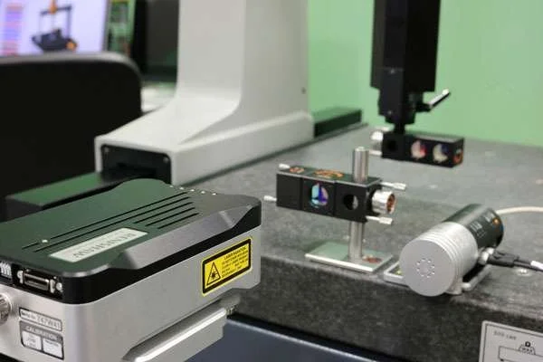
A laser interferometer is a precision instrument used to detect linear and angular deviations over distance with nanometer resolution. The setup includes a laser head, beam splitters, angular reflectors, and a target mounted to the moving axis of the CMM.
Laser Setup Components:
Laser Interferometer Head
Angular Reflector (Retroreflector)
CMM Probe and Spherical Calibration Artifact
Controlled Environmental Conditions
3. Capturing Volumetric Error Data
The interferometer is used to sweep each axis while capturing deviations between commanded positions (from the CMM) and actual positions (measured by the laser). Measurements are recorded at regular grid intervals across the full volume.
Each axis undergoes multiple passes to evaluate:
Linear displacement (along axis)
Straightness (deviation orthogonal to axis)
Angular misalignment (pitch, yaw, roll)
4. Generating and Visualizing the Error Map
The raw error data is processed and interpolated into a 3D volumetric error map, often using spline or polynomial surface fitting.
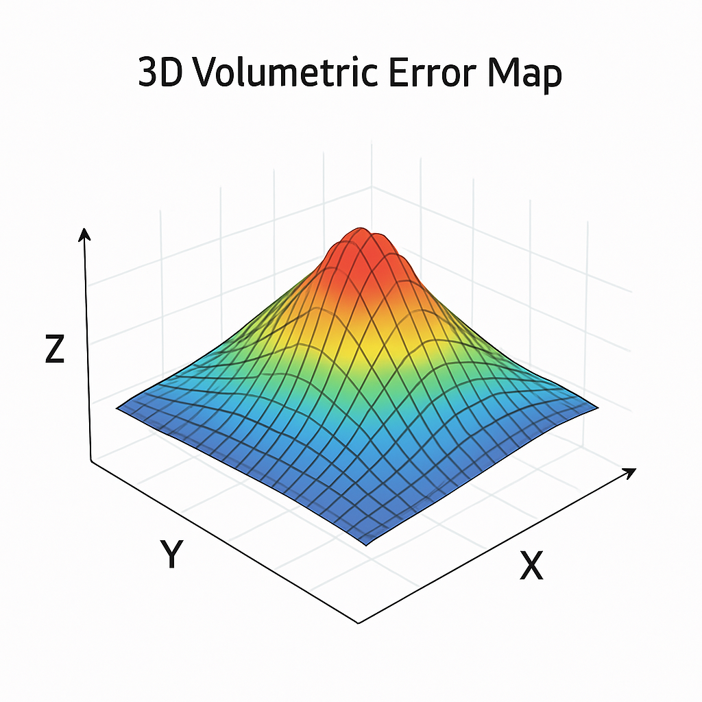
A 3D surface plot shows spatial deviations in color gradients—red for areas of high error, blue for near-zero deviation.
5. Mathematical Modeling of Error Correction
Using the error map, we construct correction matrices that apply real-time adjustments during probing and motion.
Key Formulas:
Linear Error:

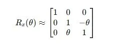
Angular Error (Small Angle Approx.):
Full Volumetric Correction:

6. Implementing Compensation into CMM Software
Once the error model is built, the compensation data is formatted (CSV, XML, or proprietary OEM format) and imported into the CMM control software.
Common Platforms:
Zeiss Calypso (uses RENISO/Calypso DAT files)
PC-DMIS (Universal CMM error map loader)
Renishaw UCC Suite (Error mapping tool integrated)
Workflow:
Import volumetric error file
Assign to current CMM configuration
Validate compensation with artifact (e.g., ball plate)
Document results and backup configuration
7. Verifying Compensation Accuracy
Validation typically involves comparing CMM readings before and after compensation using traceable reference artifacts such as:
Step Gauges
Ball Bars
Grid Plates
Case Study Example (Zeiss Accura):
Pre-compensation error: ±7 µm
Post-compensation error: ±1.5 µm
Verification via calibrated ball plate at NIST traceable lab
8. Reporting and Documentation
Final calibration and compensation steps should include:
3D volumetric error map visualization
Tables of raw vs corrected data
Certificates of traceability
Gage R&R comparison charts
These provide legal and technical confidence for audits, customers, and internal QA.
Conclusion
CMM Volumetric Compensation is a powerful, necessary procedure that ensures the long-term accuracy and reliability of your coordinate measuring machine. With proper laser setup, detailed error modeling, and verified compensation, your CMM can perform like-new across the full range of motion—even years after installation.